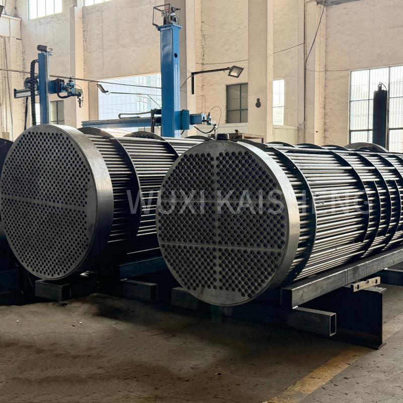

Tube sheet: tube flaring technology
2026-10-05
- Pipe flaring technology: from theory to perfect tightness
- Physics of the process and choice of flaring method
- Tube sheet preparation: a step that cannot be ignored
- Step-by-step instructions: flaring technology
- Typical defects and methods for eliminating them
- Standards and regulatory framework in the Russian Federation and the CIS
- Practical experience: from theory to production of complex equipment
- Technology Comparison: Mechanical vs Hydraulic Flaring
- Frequently asked questions (FAQ)
- Заключение и рекомендации экспертов
Pipe flaring technology: from theory to perfect tightness
Tube sheet flaring is not just a mechanical joining of metal to metal, but a critical process that determines the lifespan of heat transfer equipment for decades. In our practice, we have repeatedly encountered situations where expensive devices failed after six months of operation due to microcracks in the contact zone caused by a violation of technologyразвальцовки труб. A correctly performed operation ensures the tightness of the unit, resistance to vibration loads and effective heat transfer between media. If you are looking for an answer to the question of how to guarantee the reliability of a heat exchanger, then the key lies in strict control of the tube deformation parameters and the quality of the tube sheet surface preparation.
This article was written by engineers who have personally performed thousands of flaring cycles in production facilities in Russia, Europe and Asia. We will not retell dry definitions from textbooks. Instead, we will analyze real cases, show where fatal mistakes are most often made, and give a step-by-step algorithm of actions that will allow you to avoid emergency shutdowns of production. Understanding the physics of the flaring process distinguishes a professional technologist from an operator simply pressing a button on a machine.
Physics of the process and choice of flaring method
The essence of the technology is to create tension between the pipe and the wall of the tube sheet opening due to plastic deformation of the pipe. As the pipe expands inside the hole, it presses against the walls of the grate, creating a frictional force that holds the structure in place and prevents leaks. However, here lies the first pitfall: if the pressure is too weak, leakage will occur; if it is too strong, overdeformation will occur, leading to cracking of the material or weakening of the lattice itself.
Two main methods dominate modern industry: mechanical flaring using a mandrel and hydraulic (or pneumatic) flaring. The mechanical method, using a conical mandrel rotating inside a pipe, remains the most common for mass production due to its speed and low tooling costs. However, in our practice, we have noticed that when working with thin-walled stainless steel or titanium pipes, the mechanical method often leads to uneven thinning of the pipe wall (“helical groove effect”), which reduces the corrosion resistance of the assembly.
Hydraulic flaring, on the other hand, creates uniform radial pressure along the entire length of the contact. It is an ideal choice for highly critical components operating under high pressure or in aggressive environments. One of our clients, a manufacturer of chemical reactors, was faced with the problem of micro-leaks in devices assembled mechanically. After switching to hydraulic technology, the scrap rate decreased by 94%, although the processing time per connection increased by 15 seconds. This compromise turned out to be economically justifiable, given the cost of equipment downtime.
The choice of method depends on three factors: pipe material, wall thickness and required tension force. For carbon steels with a thickness of more than 2 mm, mechanical flaring shows excellent results. For nickel, titanium or aluminum based alloys, and for pipes with a wall thickness of less than 1.5 mm, we strongly recommend the use of hydraulic systems. Ignoring this rule is a direct road to complaints from customers.
Critical Quality Control Parameters
The success of the operation is determined not by a visual assessment, but by exact numbers. The main parameter is the percentage thinning of the pipe wall. The optimal range is from 8% to 12%. A value below 6% will not provide sufficient tension, and a value above 15% will critically weaken the pipe. The calculation is made using a formula that takes into account the initial and final internal diameter of the pipe, as well as the diameter of the hole in the grid.
The second most important indicator is the length of the flared zone. It must strictly comply with the drawing, usually protruding beyond the grid by 1-2 mm, but in no case going deep into the chamber of the apparatus, where it can create flow turbulence. The use of automated systems with depth sensors eliminates the human factor, which, according to our data, is the cause of 60% of all installation defects.
Tube sheet preparation: a step that cannot be ignored
Many technologists make the fatal mistake of focusing only on the flaring tool and forgetting about preparing the hole itself in the tube sheet. The surface of the hole must be perfectly clean and have a certain roughness. According to standardGOST R 55897-2013, the surface of the holes should not have marks directed along the axis of the pipe, as they can become centers of corrosion and paths for capillary leakage.
Before starting work, it is necessary to thoroughly clean the holes from scale, oil and oxide films. We use special brushes with abrasive bristles or chemical etching, depending on the grating material. The surface roughness (Ra) should be in the range of 3.2–6.3 µm. A surface that is too smooth (polished) reduces the coefficient of friction, which can lead to the pipe turning under load. A surface that is too rough will make it difficult to insert the pipe and may damage its outer layer during installation.
Particular attention should be paid to the geometry of the hole. The deviation from cylindricity should not exceed 0.05 mm for every 100 mm of length. In our practice, there was a case where a batch of tube sheets had elliptical holes due to wear on the supplier's drilling machine. An attempt to flare pipes into such holes led to the fact that in one part of the perimeter the tension was excessive (risk of cracks), and in the other it was completely absent (risk of leaks). The batch had to be completely rejected, which cost the company significant losses.
The clearance between the pipe and the hole before flaring begins is also critical. The recommended gap is 0.2–0.4 mm. If the gap is larger than 0.5mm, excessive deformation of the pipe will be required to fill the void, which will inevitably lead to over-deformation and reduced pipe strength. If the gap is less than 0.1mm, assembly difficulties will arise and the pipe may become stuck before the expansion process begins.
Material hardness control
The golden rule of flaring is that the pipe material must be softer than the tube sheet material. The difference in hardness (Brinell) must be at least 30 units (HB). If the pipe is harder than the grate, then during flaring it will not be the pipe that will be deformed, but the hole in the grate itself. This will result in loss of seal immediately after removal of the tool.
In situations where it is structurally impossible to make the grating harder than the pipe (for example, when using titanium pipes in a steel grating), the technology of fusing or lining the holes with a harder alloy is used. Ignoring the hardness test before starting a series is a lottery that the plant almost always loses.
Step-by-step instructions: flaring technology
Below is a detailed algorithm for performing mechanical flaring, which we use on our production lines. Following these steps allows you to achieve consistent quality even when working with new staff.
- Instrument preparation and calibration check.Before starting a shift, the operator must check the condition of the flaring head rollers. Even 0.1 mm wear on the rollers changes the cone angle and expansion force. Use a clamp gauge to check the free diameter of the head. Lubrication of the internal surfaces of the pipe is mandatory - use only specialized oils recommended by the tool manufacturer to avoid scuffing.Common mistake:the use of waste oil or grease, which contains abrasive particles and leads to scratches on the inner surface of the pipe.
- Installing the pipe and fixing the depth.Insert the pipe into the tube sheet hole until it stops at the stop collar or use the mechanical stop on the flaring machine drive. The immersion depth must be adjusted to within 0.5 mm. Incorrect installation will cause the flaring area to move relative to the plane of the grid, creating a “step” inside the apparatus that will collect contaminants and interfere with the flow of the medium.
- Beginning of the expansion process (first pass).Start the drive at low speed. Smoothly insert the head into the pipe. The pressure should increase gradually. At this stage, the initial sampling of the gap occurs. It is important to monitor the motor current (if an electric drive is used): a sharp jump in current signals a jam or improper alignment. Stop the process if you hear grinding noise - this is a sign of chips or sand getting between the rollers and the pipe.
- Basic flaring and force control.Increase speed to operating speed. The rollers should evenly press the pipe wall against the hole wall. The critical moment is when the pipe material reaches its yield point. Modern CNC machines automatically stop when a preset torque or rotation angle is reached. With manual control, the operator is guided by the feeling of resistance.Important:Never try to “press” a pipe if it seems to be loose. It is better to make a second pass with adjustment correction than to re-deform the metal once.
- Tool removal and finishing.Once expansion is complete, reverse the operation and smoothly remove the head. A sharp pull can break the tension that has just been created. Inspect the ends of the pipe: they should be smooth, without burrs. If necessary, remove the chamfer using a special countersink. Burrs are dangerous because they can come off due to flow and damage downstream pumps or valves.
- Rolling (optional, but recommended).To strengthen the connection and relieve residual stresses, it is recommended to perform the operation of rolling the end of the pipe to the plane of the grid. This creates an additional mechanical lock and improves the appearance of the unit. Rolling is performed with a special roller, which compresses the edge of the pipe at an angle of 45 degrees.
After completing all the steps, be sure to carry out selective inspection by measuring the internal diameter of the pipe with a bore gauge or by air pressure testing. In our documentation, every tenth unit is subject to mandatory leak testing with water under pressure 1.5 times higher than the working pressure.
Typical defects and methods for eliminating them
Even if the technology is followed, defects may occur. Being able to quickly diagnose a problem saves hours of downtime. Let's look at the most common cases that we encountered in the workshops.
Longitudinal cracks on the pipe.This is the most dangerous defect, often invisible to the naked eye. The reason is almost always the same - an excessive degree of flaring (wall thinning of more than 15-18%) or the presence of defects in the pipe material itself (rolled out ends). Solution: reduce the tool feed or increase the flaring pitch. Also check the certificates for the batch of pipes - perhaps the material does not correspond to the declared ductility.
Pipe tearing out of the grating due to axial force.If the pipe is easily pulled out by hand or with little tension, then the tension is insufficient. Causes: too large initial gap, low grate hardness, surface contamination with oil or oxides, or insufficient flaring zone length. Solution: increase the flaring force, sandblast the grille holes, or increase the length of the contact zone.
Pipe ellipse after flaring.The pipe becomes oval instead of round. This indicates uneven wear on the rollers of the flaring head or runout of the machine spindle. Working with such a tool is unacceptable, since contact will only be at two points, and not along the entire perimeter. Immediate replacement or grinding of the rollers and repair of the drive are required.
Scratches and risks on the inner surface.Occur due to lack of lubrication, use of dirty tools or too high rotation speed. Such defects sharply reduce corrosion resistance and create stress concentration points. In the food and pharmaceutical industries, such pipes are subject to unconditional rejection.
Effect of temperature on the process
Don't forget about the temperature factor. The coefficient of linear expansion of different metals is different. If the heat exchanger operates at high temperatures (above 300°C), then when heated, the pipe will expand more than the grate (if the pipe is steel, and the grate is made of cast iron or a special alloy with a lower coefficient of expansion), which can increase the tension and lead to metal creep. Conversely, when cooling, the interference may disappear. When designing and selecting flaring technology for high-temperature services, it is necessary to calculate thermal stresses. In such cases, a combined method is often used: flaring + flanging welding.
Standards and regulatory framework in the Russian Federation and the CIS
Work in the industrial sector of Russia and the EAEU countries requires strict compliance with regulatory documents. The main guiding document isGOST 31317-2007“Heat exchangers. General technical conditions", which regulates the requirements for the quality of connections. It is also important to considerPB 03-576-03“Rules for the design and safe operation of pressure vessels.”
According to these standards, each connection must withstand hydraulic tests without signs of leakage or permanent deformation. The documentation for the flaring process (technological map) must contain data on the flaring mode (torque, angle of rotation, number of passes) for each type of standard size. These data must be verified during technology certification.
For export products to the countries of the Eurasian Economic Union, an EAC certificate is required. Equipment manufacturers must have an ISO 9001 certified quality management system with flaring control procedures as key control points. Lack of traceability of flaring parameters for each piece of equipment can be grounds for refusal of acceptance by the customer, especially in the oil and gas sector.
We recommend regularly auditing technological processes for compliance with the latest editions of GOST. The regulatory framework is being updated, and the use of outdated techniques can lead to legal risks in case of emergency situations.
Practical experience: from theory to production of complex equipment
A deep understanding of flaring technology is the foundation for creating reliable heat transfer equipment. This is the principle that underlies the company’s work.Wuxi Kaisheng Electric Power and Petrochemical Equipment Co., Ltd.. Specializing in the design and manufacture of high-load components, the company has successfully applied the techniques described above to the manufacture of titanium shell-and-tube heat exchangers, ASME-certified pressure vessels and 316 stainless steel corrugated tube bundles.
The experience of Wuxi Kaisheng specialists confirms the importance of the correct selection of materials and assembly methods. When producing tube bundles from C46400 marine brass, copper-nickel alloys or exotic N06625 nickel alloys, the slightest deviation in flaring technology can lead to catastrophic consequences in the harsh environments of petrochemical or seawater desalination. The company uses PED and ASME certified processes to ensure high corrosion resistance and resistance to extreme temperatures and pressures. Whether it's air coolers, waste heat boilers, or complex tube sheets made from 321 steel and C70600 alloys, each product is strictly inspected from gap selection to final crimping. This approach allows us to provide customers around the world with customized solutions that work reliably for years.
Technology Comparison: Mechanical vs Hydraulic Flaring
Чтобы помочь вам принять взвешенное решение при выборе оборудования для вашего производства, мы подготовили сравнительную таблицу двух основных технологий. Данные основаны на статистике нашего сервиса за последние 3 года.
| Comparison criterion | Механическая развальцовка (Дорн) | Гидравлическая развальцовка |
|---|---|---|
| Равномерность давления | Неравномерное (точечный контакт роликов). Риск спиральных следов. | Абсолютно равномерное по всему периметру (360°). Идеальная геометрия. |
| Скорость обработки | High. Подходит для массового потока (сотни труб в смену). | Average. Требует больше времени на установку уплотнений и накачку давления. |
| Применимость к материалам | Углеродистые стали, латунь, медь. Плохо подходит для титана и хрупких сплавов. | Универсальна. Идеальна для титана, нержавейки, алюминиевых сплавов и тонкостенных труб. |
| Стоимость оснастки | Low. Ролики и дорны стоят недорого и легко заменяются. | High. Гидроголовки сложны в изготовлении и ремонте. |
| Риск повреждения трубы | Средний/Высокий (зависит от квалификации оператора). | Minimum. Система автоматически сбрасывает давление при превышении лимита. |
| Recommended area | Конденсаторы ТЭЦ, отопительное оборудование, бюджетные теплообменники. | Химическая промышленность, атомная энергетика, пищепром, оффшорные платформы. |
Как видно из таблицы, универсального решения не существует. Для завода, выпускающего 500 бытовых кондиционеров в день, гидравлика будет экономическим самоубийством. Но для единичного заказа реактора высокого давления из хастеллоя механический метод неприемлем по соображениям безопасности. Выбирайте инструмент под задачу, а не под моду.
Frequently asked questions (FAQ)
What is the minimum gap allowed between the pipe and the grille?
Оптимальный зазор составляет 0.2–0.4 мм. Зазор менее 0.1 мм затруднит сборку и может привести к задирам при вставке. Зазор более 0.5 мм потребует чрезмерной деформации трубы для его выбора, что приведет к передеформации и снижению ресурса узла. Если ваши допуски на изготовление отверстий и труб выходят за эти рамки, необходимо пересмотреть технологию механообработки или применить промежуточные втулки.
Можно ли развальцевать трубу повторно, если первая попытка неудачна?
Повторная развальцовка допускается только в том случае, если первая попытка не достигла требуемого момента затяжки (недодеформация). Вы можете сделать еще один проход с увеличенным усилием. Однако, если труба уже была передеформирована (утонение стенки превысило норму или появились трещины), повторная развальцовка категорически запрещена. Такую трубу можно только высверлить и заменить на новую. Попытка «исправить» передеформированную трубу гарантированно приведет к разрушению соединения при эксплуатации.
Is it necessary to lubricate the pipe before flaring?
Да, смазка обязательна. Она снижает трение между роликами дорна и внутренней поверхностью трубы, предотвращает задиры и обеспечивает чистоту поверхности после обработки. Используйте только те смазочные материалы, которые не содержат твердых абразивных частиц и легко смываются (если требуется чистота системы). Отсутствие смазки увеличивает усилие развальцовки на 20-30% и ускоряет износ инструмента.
Как контролировать качество без разрушающего контроля?
Основным неразрушающим методом является измерение внутреннего диаметра трубы после развальцовки с помощью нутромера и сравнение с расчетным значением. Также широко применяется метод опрессовки воздухом или водой. Визуальный осмотр торцов и проверка усилия выдергивания (на образцах-свидетелях) также входят в стандартный пакет контроля. Для критических узлов возможно применение ультразвукового контроля зоны контакта.
Заключение и рекомендации экспертов
Technologyразвальцовки трубв трубной решетке остается фундаментальным процессом в теплоэнергетике и химическом машиностроении. Несмотря на появление новых методов сварки и клеевых соединений, механическое расширение обеспечивает уникальное сочетание надежности, ремонтопригодности и экономической эффективности. Однако цена ошибки здесь крайне высока: одна негерметичная труба может вывести из строя весь многотонный аппарат.
Наш многолетний опыт подсказывает, что 80% проблем возникают не из-за плохого оборудования, а из-за нарушения дисциплины процесса: грязные отверстия, неизмеренная твердость, усталость оператора. Внедрение автоматизированных систем контроля момента и глубины, регулярное обучение персонала и строгое соблюдение карт технологического процесса — вот три кита, на которых держится качество ваших теплообменников.
Если вы планируете модернизацию производственной линии или сталкиваетесь с повторяющимися проблемами герметичности, не полагайтесь на интуицию. Проведите аудит вашей текущей технологии. Возможно, простая замена типа смазки или корректировка угла конуса дорна решит проблему, которая мучила вас месяцами.
Мы готовы поделиться своим опытом и предоставить консультации по подбору оптимального режима развальцовки для ваших конкретных условий. Надежность вашего оборудования — это результат внимания к деталям.
Contact us today, чтобы обсудить ваши задачи и получить профессиональную поддержку в области сборки теплообменного оборудования. Посетите наш разделТрубчатые теплообменникидля ознакомления с полным спектром наших решений.