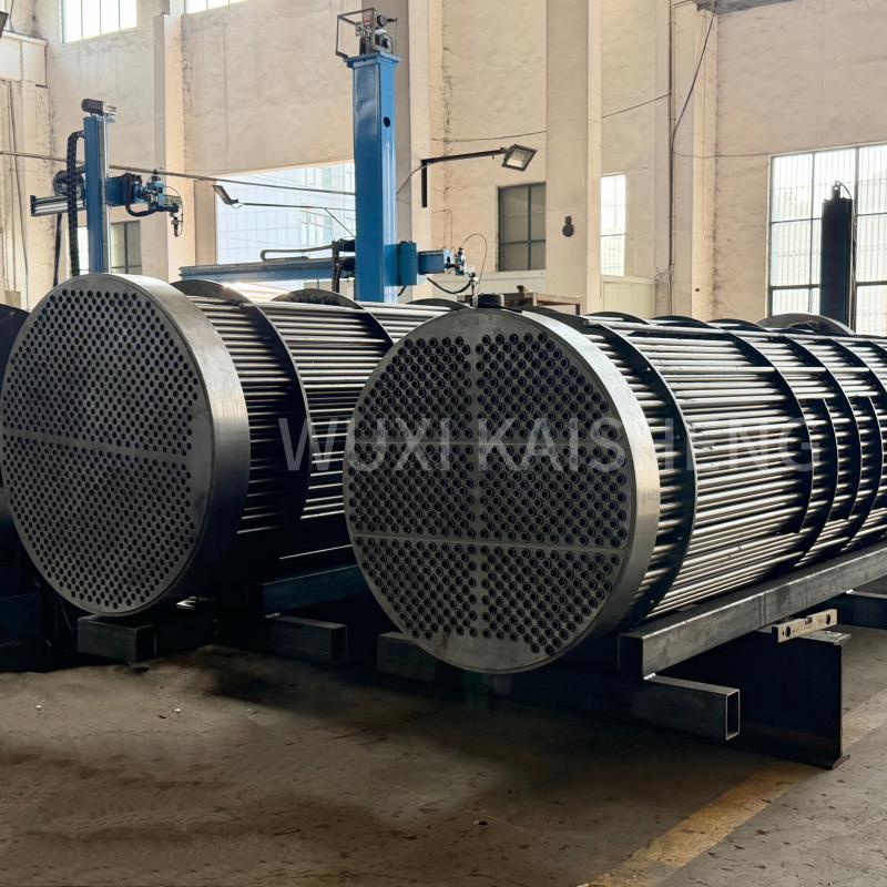

Tube sheet flaring: process automation
2026-10-06
- Why automation of tube sheet flaring is a matter of survival, not just an upgrade
- Technology gap: why hand tools no longer pass quality control
- Automated system architecture: from manipulator to integrated line
- Critical process parameters and quality control according to GOST and ISO
- Типичные ошибки внедрения и как их избежать
- Будущее отрасли: адаптивные системы и Industry 4.0
Why automation of tube sheet flaring is a matter of survival, not just an upgrade
Tube sheet flaring: Process automation has ceased to be an option for large plants and has become a must for maintaining margins in 2026. In our practice, we see a clear boundary: enterprises that continue to rely on manual labor when assembling heat exchangers lose up to 18% of profits due to defects and downtime, while the introduction of robotic systems reduces this figure to 1.5%. These are not marketing slogans, but dry mathematics that every chief engineer faces when preparing for certification according to GOST R or international ASME standards.
When the temperature in the workshop drops below +15°C, the human factor comes to the fore. The operator gets tired, the tightening force of the pneumatic tool fluctuates, and the tightness of the connection is broken. Automation eliminates this variable. It replaces the “feel of the hand” with a digital protocol where every step is recorded in a database. If you are reading this article, it means that you are already faced with the need to scale production or tighten customer requirements for the quality of welds and rolling joints.
We will not say that robots are ideal. This method has its limitations and high barriers to entry. But if your output exceeds 50 heat exchangers per year, the manual method becomes economic suicide. Below we will look at exactly how the transition from manual labor to digital control occurs, what mistakes 9 out of 10 companies make when they first attempt automation, and how to avoid losing millions of rubles at the implementation stage.
Technology gap: why hand tools no longer pass quality control
The traditional approach to flaring pipes in tubesheets was based on the experience of the individual fitter. For decades it was believed that a good master could “touch” the moment when the process was completed. In 2026, this approach is recognized as archaic and dangerous. The main problem with handheld tools is the lack of real-time torque and angle feedback. The operator focuses on the sound of the engine or the visual expansion of the pipe, which is subjective and depends on fatigue, lighting and even the mood of the worker.
In our practice, there was a case where a large oil refinery accepted a batch of 40 capacitors assembled by hand. After three months of operation, a massive leak occurred. The investigation revealed that the assembly crew was working in two shifts, and the night shift was using worn mandrels that produced less expansion. As a result, the interference was 0.08 mm instead of the required 0.12–0.15 mm. The consequences were catastrophic: line shutdown, fines and loss of supplier reputation. This incident cost the company more than 12 million rubles in direct losses, not counting reputational losses.
Automation of the tube sheet flaring process radically solves this problem. Robotic heads or stationary CNC machines operate according to a rigid algorithm. They don't get tired, distracted, or ignore instructions. The system monitors three critical parameters simultaneously: rotation speed, torque and linear movement of the mandrel. As soon as the specified moment of resistance is reached (which corresponds to the desired tension), the tool instantly stops and reverses. The human error of “overexposure”, which leads to thinning of the pipe wall and its rupture, is eliminated.
In addition, automatic systems ensure uniform force along the entire length of the tube sheet. When working manually, misalignment often occurs: the pipes in the center of the grate are flared well, but at the edges - weakly, because the operator changed the position or angle of approach. The robot moves along a programmed path with an accuracy of 0.01 mm. This is especially critical for high-pressure vessels, where uneven stresses in the grid can lead to deformation of the entire housing under load.
Another aspect that is often overlooked is documenting the process. Modern manufacturing requires traceability. The customer wants to see a quality certificate for each connection. The manual method does not provide such an opportunity: you can only sign a paper that “the work was performed by I.I. Ivanov.” The automated complex saves logs of each pass: time, date, operator number, actual tightening torque and expansion schedule. This data can be uploaded to the ERP system and attached to a report for the customer. To work with giants such as Gazprom or international oil companies, the presence of such a digital footprint is often a mandatory requirement of the tender.
However, it is worth recognizing the limitation: automation does not forgive mistakes in preparation. If the pipe is inserted crookedly or the hole in the grid is more elliptical than acceptable, the robot will still perform the cycle, but the result will be defective. The difference is that a smart system can immediately signal an anomaly in the starting torque, while a person can simply push the pipe further, exacerbating the defect. Therefore, automation requires more strict incoming control of workpieces.
Transition Economics: Payback Calculation and Hidden Costs
Many managers stop at the stage of purchasing equipment, seeing a price tag of several tens of thousands of dollars or euros. Yes, the initial investment in tube sheet flaring automation is high. The cost of one robotic cell can range from $80,000 to $250,000 depending on the configuration and brand. However, the comparison should be made not with the purchase price of an air drill ($500), but with the total cost of ownership (TCO) of the process over 3-5 years.
Let's look at the numbers. Manual flaring of one heat exchanger with a medium tube sheet density (about 300 tubes) takes a qualified team of two people approximately 12–14 hours. Taking into account overhead, salaries, taxes and equipment downtime, the cost of this operation is about $600–$700. In this case, the risk of rework is about 5–7%. An automated line performs the same work in 2.5–3 hours with the participation of one operator-adjuster. The cost drops to $150, and the defect rate is reduced to 0.5%.
A simple calculation shows that with the production of 200 devices per year, savings in operating costs alone amount to more than $90,000 annually. Plus, there are savings on materials (fewer defective pipes and gratings) and no penalties for missing deadlines. Payback for equipment in this mode occurs in 14–18 months. After that, each manufactured device brings net additional profit.
But there are also hidden costs that equipment sellers are silent about. Firstly, this is integration. A robot cannot work in a vacuum. He needs pipe preparation: trimming, chamfering, cleaning the surface to a metallic shine. If you automate only the rolling but leave the preparation manual, the bottleneck will simply move. You will have to purchase automatic machines for cutting and stripping pipes, which will increase the project budget by another 30–40%.
Secondly, maintenance and calibration. Torque and force sensors require regular verification. The mandrels wear out faster than during manual work, because the robot works intensively without pauses. Consumables (mandrels, mandrels, lubricants) become a fixed expense item. In our experience, we have seen cases where companies skimped on original mandrels by buying cheap analogues, which led to the rapid failure of the expensive robot head. Saving $200 on tooling turned out to be a $15,000 spindle repair.
Thirdly, staff training. The skilled roller operator now becomes a CNC operator. These are different competencies. We need to teach people how to program, diagnose errors, and work with HMI panels. Turnover in this new role can be high if the right incentive system is not in place. Investments in a training center or on-site training for engineers at the equipment supplier are required.
Despite these difficulties, the trend is irreversible. The market dictates the conditions: speed, quality and transparency. Companies that ignore automation risk remaining in the small-scale repair segment, where margins are minimal and competition with dumping workshops is maximum. For mass production there is only one way - robotization.
Automated system architecture: from manipulator to integrated line
The choice of equipment type for automating tube sheet flaring depends on the dimensions of your products, production series and budget. There is no universal solution that would suit everyone. There are three main directions in the industry for implementing this process, each of which has its own niche of application.
1. Robotic cells based on industrial manipulators (6 axes)
This is the most flexible solution, ideal for medium-scale production of a variety of heat exchangers. The robot (for example, KUKA, ABB, Fanuc or Chinese analogues like Estun) is equipped with a special head for flaring. The head is mounted on the flange of the last axis of the robot. The advantage of this scheme is the ability to access tube sheets of complex shapes and large dimensions, where it is impossible to bring a stationary machine. The robot can move along the apparatus, processing pipes sequentially or in groups.
The key element here is the adaptive head. It should compensate for small inaccuracies in the robot’s positioning (which always exist, even with expensive models) and ensure the alignment of the mandrel and pipe. Modern heads have floating mechanisms and force sensors that allow the robot to “feel” the entrance to the pipe. If the pipe is displaced by 0.5 mm, the robot will not break the mandrel, but will correct the trajectory. The software allows you to set flaring maps: the order of pipe processing (spiral, rows, sectors) to minimize lattice deformation from local heating or stress.
Such systems require safety guards and light barriers as the robot moves through the work area. Productivity reaches 40–60 pipes per hour depending on wall thickness and material.
2. Gantry systems and coordinate tables
For large heat exchangers, where the weight of the device does not allow it to be tilted or moved, portal systems are used. A portal with a flaring head moves over the stationary heat exchanger along the X, Y, Z axes. Sometimes a rotation axis C is added to rotate the head. This solution provides the highest positioning accuracy (up to 0.02 mm), since the rigidity of the portal is higher than that of a cantilever robot.
Portal systems are often integrated with machine vision systems. The camera scans the tube sheet before starting work, builds a hole map and adjusts the program in real time. This allows you to work with gratings where the pipe pitch has technological deviations after welding the body. Such a system is indispensable in the production of unique, one-piece devices of large diameter, where the manufacture of a conductor is not economically feasible.
The disadvantage is the high cost and large dimensions of the installation itself. A large workshop area and a strong foundation are required. The payback of such systems is only possible with a constant load or a very high cost of the final product (for example, devices for nuclear energy).
3. Specialized CNC machines and magazine heads
For mass production of typical heat exchangers (for example, for the automotive industry or household air conditioners), specialized machines are used. They represent a rigid structure into which the tube sheet is installed. The flaring head can be single (for sequential processing) or multi-spindle (simultaneous flaring of several rows).
The most productive lines are equipped with automatic tool changers and a magazine of mandrels of different diameters. The operator only loads the pipe package and fixes the grid. The machine itself determines the type of pipe using a barcode or RFID tag, selects a program and starts working. The productivity of such lines can reach 300–500 pipes per hour.
The main disadvantage is low flexibility. Changeover to a different standard size of the heat exchanger can take from 4 to 24 hours (replacement of conductors, reprogramming, setting up sensors). Therefore, such machines are profitable only when producing large batches of identical products (batch of 1000 pieces).
When choosing an architecture, it is important to consider not only current tasks, but also the prospects for product development. A robotic cell today seems redundant for simple tasks, but tomorrow it will make it possible to take orders for complex devices that competitors will not be able to make on portal machines due to their lack, and on specialized machines due to the high cost of retooling.
Critical process parameters and quality control according to GOST and ISO
Automation is meaningless without a clear understanding of the physics of the process. Setting up the robot program “by eye” will ensure that you produce defects quickly and efficiently. Flaring is a plastic deformation process and the key to success lies in interference fit.
Calculation of nominal interference
The first step is to determine the target interference value. It depends on the materials of the pipe and grid, operating pressure and temperature of the medium. The formula is simple, but the input data must be accurate. Preload N = d_hole – d_pipe_out + Δ, where Δ is the required deformation. For carbon steels, the optimal interference fit is usually 0.1–0.2 mm. For titanium or stainless steel, the values may differ due to different elastic modulus and susceptibility to work hardening.
An error in calculations at the stage of program preparation is fatal. If the interference is too small (0.25 mm for thin walls), the pipe will tear or residual stresses will arise, leading to corrosion cracking. We recommend carrying out test flaring on witness samples from the same batch of metal as the main production, and making metallographic sections to check the microstructure.
Torque Control
In automatic systems, the main stopping criterion is the torque. As the pipe expands and is pressed against the wall of the hole, the resistance to rotation of the mandrel increases. The torque graph has a characteristic appearance: a gentle rise (idling), a sharp rise (contact with metal), a plateau (plastic deformation) and a sharp rise again (yield point, beginning of fracture).
The task of automation is to stop at the end of the “plateau”, but before the start of the second sharp increase. Modern controllers allow you to set not just a limit torque, but a torque profile. For example: “acceleration to 5 Nm, then a smooth increase to 12 Nm at a speed of 0.5 Nm/sec, holding for 0.2 sec, reverse.” This algorithm ensures that the metal is “settled” and spring-back is minimal.
It is important to consider friction. Lubrication is critical. The use of incorrect lubrication or its absence changes the coefficient of friction, and the moment of stopping will occur earlier or later than necessary, with the same actual tension. Automated systems often have lubricant dispensers that apply a strictly regulated amount of compound to the mandrel before each cycle. This eliminates the variability inherent in manual brush lubrication.
Geometric control and ovality
After flaring, it is critical to check the geometry. The pipe should not become oval. The ovality tolerance is usually no more than 1% of the diameter. In automatic lines this control can be built-in. Laser scanners or probes measure the diameter of the pipe immediately after passing the mandrel. If the value is out of tolerance, the system marks that pipe as defective and alerts the operator. In advanced systems, the robot may even try to correct the situation with a second pass with correction, although this is risky due to work hardening.
The protrusion of the pipe above the grille is also controlled (tube projection). It must be uniform for subsequent welding. Автоматика следит за глубиной погружения дорна, гарантируя, что зона развальцовки заканчивается точно на нужном расстоянии от зеркала решетки.
Стандарты и сертификация
При работе на экспорт или с госзаказом необходимо руководствоваться конкретными стандартами. В России это ГОСТ Р 53677-2009 (Нефтяная и газовая промышленность. Кожухотрубные теплообменники) и ПБ 03-576-03 (Правила устройства и безопасной эксплуатации сосудов, работающих под давлением). В международной практике — ASME Section VIII Div. 1 и TEMA (Tubular Exchanger Manufacturers Association).
Автоматизированная система должна позволять настраивать параметры в соответствии с требованиями этих стандартов. Например, TEMA требует определенных значений минимального натяга для разных классов аппаратов (R, C, B). Программа робота должна иметь библиотеку этих стандартов, чтобы оператор не мог случайно выбрать неверный режим. Наличие протоколов испытаний, сгенерированных машиной, упрощает процедуру приемки надзорными органами (Ростехнадзор и др.).
Типичные ошибки внедрения и как их избежать
Переход на автоматизацию сопряжен с рисками, которые не очевидны на первый взгляд. Анализ неудачных проектов показывает, что большинство проблем связано не с техникой, а с организацией процессов и человеческим фактором.
Ошибка №1: Игнорирование подготовки кромок
Робот не умеет заталкивать трубу в отверстие с заусенцами или грязью. Если труба входит с усилием уже на этапе сборки, дорн при развальцовке получит перекос. Результат — односторонняя развальцовка и протечка. Решение: автоматизация должна начинаться с участка подготовки труб. Внедрение станков для торцовки и снятия фаски с контролем длины вылета обязательно. Поверхность трубы и отверстия решетки должна быть очищена до степени Sa 2.5 (по ISO 8501-1). Любая окалина или масло изменят коэффициент трения и сведут на нет точность управления моментом.
Ошибка №2: Отсутствие калибровки датчиков
Датчики момента и силы подвержены дрейфу. Температурные колебания в цеху влияют на их показания. Многие заводы настраивают робот один раз при пусконаладке и забывают о нем на годы. Через полгода программа работает с ошибочными данными. Регламент должен предусматривать еженедельную проверку эталонными динамометрическими ключами и ежемесячную полную калибровку системы. Без этого «цифровой двойник» расходится с реальностью.
Ошибка №3: Неправильный выбор дорнов
Дорн — это расходный материал, но к нему относятся как к оснастке. При автоматизации износ дорнов ускоряется. Геометрия рабочих конусов меняется, появляются риски. Работа изношенным дорном дает нестабильный момент. Необходимо вести учет ресурса каждого дорна (количество циклов) и выбраковывать их строго по регламенту, а не по внешнему виду. Использование твердосплавных дорнов вместо быстрорежущей стали увеличивает ресурс в 5–10 раз, что окупает их высокую цену.
Ошибка №4: Сопротивление персонала
Рабочие воспринимают робота как угрозу рабочим местам. Это ведет к саботажу: «случайные» сбои, неправильная загрузка, игнорирование инструкций. Важно менять нарратив: робот не заменяет людей, он убирает тяжелый, монотонный труд. Оператор робота — это более квалифицированная и высокооплачиваемая должность. Нужно вовлекать лучших вальцовщиков в процесс наладки, делать их экспертами по новому оборудованию. Их опыт («чувство металла») нужен для настройки алгоритмов, которые потом будет исполнять робот.
Будущее отрасли: адаптивные системы и Industry 4.0
То, что мы наблюдаем сейчас, — это только начало эволюции. Следующий этап автоматизации развальцовки трубной решетки — полная адаптивность и интеграция в единую цифровую экосистему завода.
Уже сегодня появляются системы с искусственным интеллектом, которые анализируют тысячи предыдущих циклов развальцовки и самостоятельно корректируют параметры для каждой конкретной трубы. Учитывая, что свойства металла в пределах одной плавки могут немного различаться, ИИ способен подстраивать момент остановки индивидуально, обеспечивая идеальный натяг в 100% случаев. Такие системы обучаются на лету: если датчик контроля герметичности на следующем этапе выявляет микро-протечку, алгоритм автоматически ужесточает допуски для следующей партии.
Интеграция с MES-системами (Manufacturing Execution System) позволяет управлять производством в реальном времени. Диспетчер видит статус каждого теплообменника: «развальцовка завершена, параметры в норме, готов к сварке». Это сокращает время прохождения заказа по цеху и позволяет реализовывать концепцию «единичного потока», избавляясь от складов незавершенного производства.
Также развивается направление коллаборативных роботов (коботов). В отличие от тяжелых промышленных манипуляторов, коботы могут работать в одном пространстве с человеком без защитных клеток. Это позволяет создавать гибридные рабочие места, где человек выполняет сложную сборку и установку труб, а кобот следует за ним и выполняет развальцовку. Это промежуточный этап для предприятий, которые не готовы к полномасштабной автоматизации, но хотят повысить эргономику и качество.
В заключение, автоматизация развальцовки трубной решетки — это сложный, но необходимый шаг для любого производителя теплообменного оборудования, стремящегося к лидерству. Это не просто покупка робота, это перестройка всей технологии, культуры производства и системы контроля качества. Те, кто сделает это грамотно, получат непреодолимое преимущество в виде себестоимости и надежности продукции. Те, кто останется в прошлом, будут постепенно вытеснены с рынка крупными заказами.
Реализация таких высоких стандартов качества и технологической точности требует не только современного оборудования, но и глубокой экспертизы в материаловедении и проектировании. Именно этим занимаетсяWuxi Kaisheng Electric Power and Petrochemical Equipment Co., Ltd.. Компания специализируется на разработке и производстве сложного теплообменного оборудования для самых требовательных отраслей: от нефтепереработки и нефтехимии до судостроения и опреснения морской воды.
В портфеле решений «Уси Кайшэн» — титановые кожухотрубные теплообменники, высоконапорные аппараты стандарта ASME, гофрированные трубные пучки из нержавеющей стали 316, а также изделия из экзотических сплавов, таких как морская латунь C46400, медно-никелевые сплавы и никелевый сплав N06625. Особое внимание уделяется производству качественных трубных решеток из стали 321, латуни C46400 и сплава C70600, которые являются фундаментом надежного теплообменника. Вся продукция сертифицирована по международным стандартам PED и ASME, отличаясь исключительной коррозионной стойкостью и способностью работать в условиях экстремальных давлений и температур. Предлагая индивидуальные решения и стабильное качество для заказчиков по всему миру, «Уси Кайшэн» демонстрирует, как сочетание передовых материалов и строгого контроля процессов позволяет создавать оборудование, готовое к интеграции в самые современные автоматизированные линии.
Если вы рассматриваете возможность модернизации своего производства и хотите получить детальный аудит текущего процесса развальцовки с расчетом экономической эффективности внедрения роботизированной ячейки, наши эксперты готовы провести консультацию. Мы проанализируем вашу номенклатуру, предложим оптимальную конфигурацию оборудования и поможем избежать типичных ошибок интеграции.
Contact us todayдля обсуждения вашего проекта автоматизации. Также рекомендуем ознакомиться с нашим материалом оавтоматизации сварки трубных пучков, который логически дополняет процесс сборки теплообменников.