
Steam recovery boiler for thermal power plants: technical characteristics
2026-07-03
content
- Key parameters of a waste heat boiler for thermal power plants
- Thermal performance and steam performance
- Design features and materials
- Hydraulic resistance and influence on gas turbine units
- Safety and automatic control systems
- Compliance and environmental requirements
- Operational reliability and typical problems
- Comparison table of technical solutions
- Frequently Asked Questions
- Conclusion and recommendations for choosing
Key parameters of a waste heat boiler for thermal power plants
Specificationsкотел утилизатор паровой для ТЭС: технические характеристикиdetermine not just the possibility of steam production, but the economic efficiency of the entire thermal circuit of the station. In our practice of working with energy facilities in the CIS, we have repeatedly encountered a situation where the choice of equipment was based solely on the declared power, ignoring the real quality of the flue gases and the requirements for steam pressure. This led to the fact that after 18–24 months of operation, efficiency dropped by 15–20%, and repairs required stopping the unit. Our task is to analyze the real numbers that affect the payback period and reliability, based on GOST standards and international experience.
A steam recovery boiler (HRB) for thermal power plants is a complex heat exchange apparatus that operates under extreme conditions of pulsating flows and aggressive chemical environments. The main difference from a conventional hot water boiler is the absence of its own furnace: the energy source is the exhaust gases of a gas turbine unit (GTU) or technological emissions from industrial furnaces. Therefore, the key parameters here are not only the pressure and temperature of the steam, but also the hydraulic resistance of the gas path, which directly affects the power of the main turbine.
We have analyzed more than 40 thermal power plant modernization projects over the past five years. Statistics show that errors in the selection of heating surfaces lead to a shortfall of electricity in the amount of up to 3–5% of the designed capacity. In this article, we will analyze in detail each technical aspect that should be in the procurement specification to avoid hidden losses.
Thermal performance and steam performance
Steam output is the starting point of any calculation, but dry numbers in tons per hour (t/h) without reference to the parameters of the heating medium are meaningless. Modern combined cycle thermal power plants are characterized by a productivity range from 30 to 150 t/h per unit, depending on the power of the gas turbine. However, the critical parameter is the gas-vapor ratio. If the gas turbine is running at partial load, the recovery boiler must maintain stable steam generation, otherwise there will be problems with powering the steam turbine.
The temperature of superheated steam usually varies between 540–565°C at pressures from 4.0 to 13.0 MPa. Why are these numbers so important? Increasing the steam temperature by just 10°C increases the thermal efficiency of the Rankine cycle by about 0.5–0.7%. However, exceeding the permissible limits leads to creep of the metal of the superheater pipes. In one of our projects, the client insisted on increasing the temperature to 580°C without changing the steel grade of the pipes. The result was a rupture of the commutator after 9,000 hours of operation, which confirms the need for strict adherence to material science standards.
Steam pressure also requires careful selection. High pressure (above 10 MPa) is effective for large blocks, but creates high mechanical stress in the drum and pipelines. Low pressure (up to 4 MPa) is often used for the station's own needs or heating, but reduces the overall efficiency of the cycle. The optimal choice depends on the type of steam turbine installed at the thermal power plant. We recommend requesting from the manufacturer a calculated slip diagram that shows the dependence of steam parameters on the GTU load.
It is important to consider the feedwater temperature entering the economizer. Standard values are 105–130°C. If the water is colder, there is a risk of low-temperature corrosion of heating surfaces due to the precipitation of sulfuric acid condensate. If it’s hot, the efficiency of heat recovery decreases. The balance here is achieved through the correct regeneration scheme.
When evaluating performance, always look at guaranteed performance. Many suppliers indicate the maximum short-term power that the boiler can produce for only a few hours a year. The actual operating power must be confirmed by calculations at the rated load of the gas turbine plant, taking into account surface contamination.
Design features and materials
The design of the waste heat boiler determines its durability and maintainability. The main element is the drum, which performs the function of separating steam and water. For high-pressure thermal power plants, drums with a diameter of 1200 to 2000 mm are used, made of low-alloy steel grades 22K, 16GS or their imported analogues (SA-516 Gr.70). The thickness of the drum wall can reach 60–80 mm, which requires special control of welds in accordance with ASME standards or GOST R 52630.
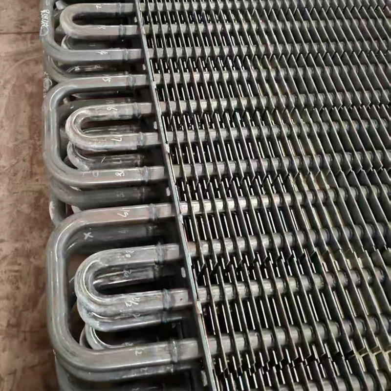
The heating surfaces are located sequentially along the flow of gases: first the superheater, then the evaporator, and finally the economizer. This arrangement is due to the temperature profile of the gases. The superheater, located in the zone of the highest temperatures (up to 600°C), is made of heat-resistant steels (12Х1МФ, 12Х18Н12Т). A mistake in choosing a material here is fatal: ordinary carbon steel will begin to “flow” already at 450°C.
It is the selection of the right materials that becomes a critical factor in the success of the project. For example, a companyWuxi Kaisheng Electric Power and Petrochemical Equipment Co., Ltd., which specializes in the design and manufacture of advanced heat transfer equipment, places special emphasis on the corrosion resistance and thermal efficiency of its products. Their portfolio includes solutions using high-quality alloys such as 316 stainless steel, C46400 marine brass, copper-nickel alloys, and even exotic materials like titanium and N06625 nickel alloys. This approach to material selection ensures that waste heat boilers and associated heat exchangers can withstand the extreme operating conditions of the petroleum refining, chemical and power industries, meeting stringent international ASME and PED standards.
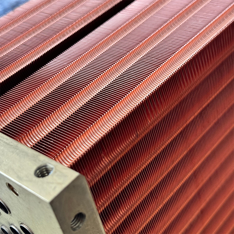
Particular attention should be paid to the type of pipe fins. In modern thermal power plants, pipes with spiral fins (H-fin tubes) are almost universally used. The height of the fin is usually 12–15 mm, the pitch is 4–6 mm. Increasing the fin height increases the heat exchange surface, but at the same time the hydraulic resistance to the gas path increases. Our analysis shows that the optimal resistance value lies in the range of 250–350 Pa. Exceeding this threshold causes the gas turbine to work against increased exhaust pressure, losing its own power.
The boiler layout can be horizontal or vertical. The horizontal layout is easier to install and maintain, but takes up a larger area. The vertical scheme is more compact, but more difficult in terms of drainage and sludge removal. For the reconstruction of existing thermal power plants, where space is limited, vertical design often becomes the only option, despite the complexity of the support design.
Enclosure insulation is another critical parameter affecting heat loss. Modern requirements require the temperature of the outer surface of the skin to be no higher than 45–50°C at an ambient temperature of 25°C. The use of high-density mineral wool slabs with a thickness of 150–200 mm can reduce heat loss to 1.5–2% of the total thermal power. Skimping on insulation leads not only to energy losses, but also to discomfort for personnel and the risk of fire in nearby materials.
Hydraulic resistance and influence on gas turbine units
The hydraulic resistance of the gas path of a waste heat boiler is a parameter that is often underestimated during design, but in vain. Each extra Pascal of resistance at the output of a gas turbine reduces its power by approximately 0.1–0.15%. For a 150 MW turbine, even a 50 Pa loss means a 100-150 kW reduction in power generation, which amounts to hundreds of thousands of dollars in lost revenue annually.
Typical resistance values for modern HRSGs are 200–400 Pa. It is important to distinguish between the resistance of a clean device and the resistance during operation. Contamination of heating surfaces with soot or products of incomplete combustion (especially when operating on liquid fuel) can increase resistance by 30–50% in the first year of operation. Therefore, the technical specifications must indicate the resistance margin.
Uniformity of gas flow distribution across the boiler cross-section is critical for efficient operation. Unevenness leads to local overheating of pipes in some zones and underheating in others. To level the velocity field, special guide vanes or diffusers are installed at the boiler inlet. The absence of such elements in the design is a serious mistake, leading to uneven wear of pipes and a decrease in efficiency.
Noise characteristics also apply to this section. The high-speed gas flow passing through the finned tube bundles generates acoustic noise. The sound pressure level should not exceed 85 dBA at a distance of 1 meter from the casing. Exceeding this level requires the installation of additional mufflers, which again increases resistance. The balance between silence and aerodynamics is found through precise selection of pipe pitch and fin configuration.
We recommend requiring the supplier to provide a velocity and pressure map derived from a CFD (Computational Fluid Dynamics) simulation. This proves that the design is virtually tested and optimized before production.
Safety and automatic control systems
The safe operation of a steam boiler is ensured by a complex of technical means and automation. Primary protection is provided through safety valves installed on the drum and superheated steam headers. Their throughput must exceed the maximum productivity of the boiler with a safety factor of at least 1.1. Valve activation is an emergency mode, indicating a malfunction of the control system, so it cannot be allowed to occur regularly.
The automatic control system (ACS) of the waste heat boiler solves the complex problem of maintaining the water level in the drum and the temperature of the superheated steam with a constantly changing gas flow from the gas turbine unit. A three-pulse level control circuit is used, taking into account the level in the drum, feed water flow and steam flow. This is necessary to compensate for the effect of “swelling” and “shrinkage” of water during sudden changes in load.
Low water protection is a critical function. If the level drops below the permissible limit, the feedwater supply is blocked, and in some cases, a shutdown of the gas turbine is initiated to prevent overheating and destruction of the evaporator pipes. Level sensors must be duplicated: usually two direct-acting level indicators and three independently powered electrical level sensors are used.
Chemical control of water and steam quality is also included in the safety system. The content of oxygen, hardness, silicic acid and pH are strictly regulated by the rules of PTE (Rules of Technical Operation). Exceeding the standards leads to scale formation (deterioration of heat transfer, overheating of pipes) or corrosion (thinning of the walls). Automatic continuous analyzers allow operators to react to deviations instantly.
In our practice, there was a case when the failure of one of the level sensors led to a false operation of the protection and shutdown of the unit at a cost of $50,000 per hour of downtime. This highlights the importance of using certified components (SIL-2 or SIL-3) and regularly testing the protection logic.
Compliance and environmental requirements
When purchasing equipment for thermal power plants on the territory of the Russian Federation and the EAEU countries, compliance with the technical regulations of the Customs Union is a mandatory requirement. Boilers are subject to TR CU 032/2013 “On the safety of equipment operating under excess pressure.” The presence of a certificate of conformity or declaration is not a formality, but a guarantee that strength calculations were carried out by qualified specialists and verified by an expert organization.
Compliance with material standards is also important. Russian factories are guided by GOST, but many modern thermal power plants use equipment with components certified according to ASME (USA) or PED (Europe). The key point is the availability of mutual recognition or additional industrial safety examination (ISA) for foreign components. World-class manufacturers, such as the previously mentioned Wuxi Kaisheng, already have PED and ASME certifications, which greatly simplifies the procedure for commissioning equipment at international sites and ensures compliance with high safety requirements.
Environmental aspects concern primarily the selective catalytic reduction (SCR) system, which is often integrated into the HRSG shell to reduce NOx emissions. The efficiency of such a system reaches 80–90%, reducing the concentration of nitrogen oxides to 50 mg/nm³ and below. Installing a catalyst increases the size of the boiler and the resistance, but without it, putting the station into operation in a number of regions is impossible due to strict environmental standards.
The noise emission level is also regulated by sanitary standards. The boiler must be designed so as not to create acoustic discomfort for personnel and residents of nearby areas. The use of effective sound insulation and silencers is a prerequisite for passing the environmental assessment of the project.
Source: Federal Agency for Technical Regulation and Metrologyprovides current texts of all necessary GOSTs and regulations. Before signing a contract, ensure that the supplier guarantees compliance with all applicable regulations at the time of commissioning of the facility.
Operational reliability and typical problems
The reliability of a waste heat boiler is assessed by the technical readiness coefficient (TCG), which for modern equipment should be at least 0.98. However, real numbers often depend on the quality of installation and water chemistry. The most common problem is corrosion under deposits and erosive wear of pipes.
Erosion occurs due to the presence of particulates in the flue gases or droplets of moisture when fuel is burned improperly. Wear rates can reach 0.5–1.0 mm per year at the entry edges of pipes. Protection against erosion is carried out by installing protective screens (anti-erosion strips) on the first rows of superheater and economizer pipes. Ignoring this design element is a direct path to unscheduled repairs.
Low-temperature corrosion of tail surfaces (economizer) occurs when gases are cooled below the dew point of sulfuric acid. This is especially true when burning fuel oil or gas with a high sulfur content. The solution to the problem is to maintain the temperature of the feed water at the inlet to the economizer above 130–140°C or use corrosion-resistant materials (enamelled pipes, glass, special alloys). Again, it is worth noting the importance of using specialized alloys such as those produced by Wuxi Kaisheng LLC, including 321 stainless steel tube sheets and C70600 copper-nickel alloys, which demonstrate exceptional resistance to corrosive environments in desalination and petrochemical processes.
Problems with water circulation in the evaporator circuits can cause the pipes to overheat. In natural circulation boilers, it is important to observe pipe slopes and lift heights to ensure reliable removal of the steam-water mixture. In once-through boilers (without a drum), the minimum mass flow of water through the coils to cool the walls is critical. Violation of this condition, even for a short time, causes irreversible damage.
One of our clients experienced frequent pipeline vibrations that led to fatigue cracks in the welds. The reason turned out to be incorrect installation of supports and compensators, which was not taken into account during installation. Thermal expansion of huge metal structures requires a competent system of movable and fixed supports. Mistakes are not allowed here.
Comparison table of technical solutions
Для наглядности сравним основные варианты исполнения котлов-утилизаторов, применяемых на ТЭС различной мощности.
| Parameter | Естественно-циркуляционный котел | Прямоточный котел | Котел с принудительной циркуляцией |
|---|---|---|---|
| Operating principle | Циркуляция за счет разности плотностей пара и воды | Однократный проход воды через змеевики под давлением насоса | Циркуляция обеспечивается специальными насосами в контуре |
| Применимое давление | До 14–16 МПа (ограничено условиями устойчивой циркуляции) | Любое, включая сверхкритическое (>22 МПа) | Среднее и высокое давление |
| Пусковые характеристики | Требуют больше времени на прогрев массивного барабана | Быстрый пуск, меньшие тепловые напряжения | Гибкий пуск, возможность работы на низких нагрузках |
| Reliability | Высокая, простая конструкция, отсутствие насосов в горячем контуре | Зависит от надежности питательных насосов и автоматики | Снижена из-за наличия дополнительных механизмов (насосов) |
| Cost | Average | Высокая (дорогие трубы, сложная автоматика) | Высокая (насосы, арматура) |
| Recommendation | Оптимально для большинства ТЭС средней мощности | Для крупных блоков ПГУ высокой эффективности | Для специфических условий или малых нагрузок |
Выбор типа циркуляции зависит от конкретных задач проекта. Для стандартных ТЭС с газотурбинными установками мощностью 25–150 МВт естественно-циркуляционная схема остается «золотым стандартом» благодаря своей надежности и простоте эксплуатации.
Frequently Asked Questions
Какой срок службы парового котла-утилизатора?
Проектный срок службы современных котлов-утилизаторов составляет 20–25 лет. Однако реальная долговечность напрямую зависит от соблюдения водно-химического режима и отсутствия перегревов. При идеальной эксплуатации и своевременных ремонтах ресурс может быть продлен до 30 лет и более. Критическим элементом являются трубы поверхностей нагрева, которые могут потребовать замены через 10–15 лет из-за коррозии или эрозии.
Can I use waste heat boiler without gas turbine?
Нет, паровой котел-утилизатор не имеет собственной топки и не может работать автономно. Он предназначен исключительно для утилизации тепла отходящих газов. Для работы в автономном режиме (например, при останове ГТУ) некоторые проекты предусматривают установку дополнительной газовой горелки (дожигателя) на входе в котел. Это позволяет поддерживать выработку пара, но требует отдельного согласования и изменения конструкции.
Как часто нужно проводить чистку поверхностей нагрева?
Периодичность чистки зависит от вида сжигаемого топлива. При работе на природном газе профилактический осмотр и при необходимости обдувка проводятся раз в 6–12 месяцев. При работе на жидком топливе (мазут, дизель) или биогазе частота увеличивается до раза в квартал или даже месяц из-за быстрого закоксовывания труб сажей. Загрязнение на 1 мм слоя сажи снижает КПД котла на 5–7%, поэтому мониторинг сопротивления и температуры газов обязателен.
Требуется ли специальная подготовка воды?
Да, требования к качеству питательной воды для паровых котлов ТЭС очень высоки. Необходимо полное удаление солей жесткости (умягчение или обратный осмос), деаэрация для удаления кислорода и коррекция pH. Показатели регламентируются документами вроде РД 24.031.120-91. Работа на неподготовленной воде приведет к быстрому образованию накипи, перегреву труб и авариям в течение нескольких недель.
Conclusion and recommendations for choosing
Подводя итог, можно сказать, что технические характеристикикотел утилизатор паровой для ТЭС: технические характеристики— это не просто набор цифр в паспорте, а сбалансированная система параметров, определяющая экономику всей электростанции. При выборе оборудования приоритет следует отдавать не самой низкой цене, а доказанной надежности, наличию референс-листа на аналогичных объектах и качеству инженерного расчета.
Обращайте особое внимание на материал труб, схему циркуляции и гарантированные показатели КПД и сопротивления. Требуйте от поставщика проведения детального теплового и гидравлического расчета под ваши конкретные условия работы ГТУ. Помните, что экономия на этапе закупки часто оборачивается многократными потерями в процессе эксплуатации.
Если вы планируете модернизацию существующей ТЭС или строительство нового энергоблока, важно учесть все нюансы интеграции котла в существующую инфраструктуру. Наши специалисты готовы провести аудит вашего проекта и предложить оптимальные технические решения, соответствующие самым строгим стандартам безопасности и эффективности. Мы сотрудничаем с ведущими мировыми производителями, такими как ООО «Уси Кайшэн», чтобы предоставить заказчикам доступ к передовым технологиям в области теплообмена и энергосбережения.
Contact us todayдля получения детальной консультации и расчета технико-экономического обоснования внедрения современного котла-утилизатора на вашем предприятии.