
Exhaust gas recovery boiler: connection diagram and installation
2026-07-03
- A direct answer to the question about connection and installation
- Preparation for installation: critical parameters and tools
- Typical connection diagram for an exhaust gas recovery boiler
- Step-by-step instructions for installing equipment
- Common connection errors and their consequences
- Technical requirements and safety standards
- Economic efficiency and payback of the project
- Frequently Asked Questions
- Conclusion and recommendations for choosing a supplier
A direct answer to the question about connection and installation
The exhaust gas recovery boiler requires strict adherence to the sequence: insertion into the exhaust manifold with compensation for temperature expansion, installation of a bypass line to protect against condensation during cold engine starts, and installation of a frequency-controlled circulation pump. An error in calculating the dew point or ignoring the hydraulic resistance of the heat exchanger will lead to corrosion of the tubular bundles after 6–8 months of operation. We strongly recommend that a preliminary thermal calculation be carried out taking into account the actual operating schedule of the diesel generator, and not its passport data, since a load of 40% often causes the greatest number of problems with acid corrosion.
In our practice of implementing heat recovery systems at industrial facilities in the CIS, we encountered a situation where the customer saved on flue gas outlet temperature sensors. The result was overcooling of the heat exchange surface below 140°C, precipitation of sulfuric acid and through corrosion of the casing in one heating season. This incident taught us that the connection diagram for an exhaust gas recovery boiler cannot be universal; it must be adapted to the specific fuel composition and operating mode of the heat source. Below we will examine in detail the technical nuances that distinguish professional installation from a makeshift installation that can damage the main engine.
Preparation for installation: critical parameters and tools
Before any installation work begins, an audit of the existing exhaust system must be carried out. The exhaust gas recovery boiler creates additional aerodynamic resistance, which can reach 3–5 kPa depending on the design of the heat exchanger. If the back pressure exceeds the values allowed by the engine manufacturer (usually 6–8 kPa for turbodiesels), this will lead to overheating of the exhaust valves and a reduction in unit power by 10–15%. Therefore, the first step is always to measure the static pressure in the exhaust tract and compare it with the engine data sheet.
For high-quality installation, you will need a specific set of tools and materials, the absence of which will make the work impossible or dangerous. Be sure to prepare a welding machine for working with AISI 321 or 08Х18Н10Т stainless steels, since ordinary ferrous metals quickly burn out in the exhaust gas environment at temperatures above 400°C. Temperature expansion compensators (bellows units) are also needed, which dampen engine vibration and linear expansion of pipes when heated to 500°C. Ignoring this element is the most common cause of failure of welds in the first weeks of operation.
Pay special attention to thermal insulation. Pipelines from the engine to the waste heat boiler must have multi-layer insulation with a thickness of at least 50 mm with an aluminum screen. Heat losses in the gas delivery section reduce the overall efficiency of the recovery system. In our projects we use foil-coated basalt mats that can withstand temperatures up to 700°C. This is not just an energy efficiency requirement, but also a fire safety measure, especially if the route runs near flammable materials or in personnel areas.
Required list of equipment and materials
- Vibration compensators:Mandatory for installation immediately after the engine flange. Without them, vibration is transmitted to the boiler body, causing fatigue failure of the pipe metal.
- Shut-off valves with electric drive:The bypass line requires fast-acting valves that can switch the flow of gases in 2-3 seconds during an emergency stop of the pumps.
- Dew point sensors:At least two sensors (at the gas inlet and outlet) for automatic control of the return water temperature.
- Steam traps:Installed at the bottom point of the boiler to collect and remove aggressive condensate into a neutralization tank.
- Insulation materials:Certified non-flammable materials with a melting point above the operating temperature of the gases.
Typical connection diagram for an exhaust gas recovery boiler
The connection diagram for an exhaust gas recovery boiler is built around the principle of protecting the heat exchanger from low-temperature corrosion. The main task is to prevent the inner surface of the pipes from cooling below the dew point temperature of the sulfuric acid vapor contained in the gases. This temperature is usually 130–150°C for diesel fuel with a sulfur content of up to 0.5%. If the water entering the boiler is colder (for example, 60°C from the heating return line), aggressive condensate will instantly form on the walls of the pipes, corroding the metal at a rate of up to 1 mm per year.
To avoid this, a circuit with a three-way mixing valve or a separate heating circuit is used. Cold water from the return line is not supplied directly to the waste heat boiler. It is first mixed with hot water from the boiler outlet until a safe inlet temperature is reached (minimum 145–150°C). Only after this the coolant enters the heat exchanger. This hydraulic piping ensures that even when starting a cold system, the pipe walls will remain hot and dry. This is a fundamental rule, violation of which will void any warranty from the equipment manufacturer.
The second critical element of the circuit is the bypass flue. It is a parallel pipeline with a damper that allows exhaust gases to flow past the boiler. This is necessary in three cases: during an emergency stop of circulation pumps, when repairing the boiler without stopping the engine, and when the engine is operating at low loads, when heat recovery is impractical. Automation must control this damper: when water flow falls or gas pressure increases, the bypass damper opens, releasing gases directly into the atmosphere through the muffler. This prevents the heat exchanger from overheating and the engine blowing out.
Algorithm of operation of the automatic protection system
- Parameter monitoring:The controller constantly reads data from gas inlet/outlet temperature sensors, inlet/outlet water temperature and exhaust tract pressure.
- Checking start conditions:The system allows the supply of gases to the boiler only if the return water temperature is above the set minimum (for example, 145°C) and the circulation pump is running.
- Failover:In the event of a power outage or pump failure, the electric bypass damper actuator receives a signal to open (a spring return to the open position is often used).
- Condensation protection:If the outlet temperature of the gases drops below 160°C, the system automatically increases the inlet temperature by restricting the water flow or increasing the hot water addition.
- Alarm:In case of critical deviations (pipe breakdown, water boiling), the system gives a light and sound signal to the operator and sends a telegram to the control room.
Step-by-step instructions for installing equipment
Installation of an exhaust gas recovery boiler is a process that requires highly qualified welders and instrumentation engineers. We have developed step-by-step regulations based on the experience of installing more than 200 units of similar equipment. Following these steps will minimize the risk of errors. Remember that each stage must be accepted by the technical supervision service with the preparation of a hidden work report, especially for welds inside the insulation.
- Installation of supporting structures and foundation.
Waste heat boilers have significant weight, especially when filled with water. The foundation must be designed for static load plus dynamic vibrations from a running engine. We use anti-vibration pads between the boiler body and the support frame. It is important to ensure the installation is horizontal with an accuracy of 2 mm per meter of length to avoid stagnation of water in individual sections of the heat exchanger, which can lead to local overheating and rupture of pipes. Incorrect installation of supports is a common cause of distortion and destruction of flange connections. - Installation of gas path and compensators.
At this stage, a cut into the existing exhaust manifold is made. It is strictly forbidden to weld the boiler rigidly to the engine. A bellows compensator must be installed between the engine output flange and the boiler inlet. It compensates for axial displacement of up to 20–30 mm when heated and dampens high-frequency vibration. Welds are made using argon arc welding with full penetration of the weld root. After welding, quality control by capillary flaw detection (color flaw detection) is required to identify microcracks. - Hydraulic piping and installation of pumping equipment.
Connecting the water circuit begins with installing shut-off valves and mud traps. Coarse filters with a mesh size of no more than 1 mm must be installed in front of the pumps, since the entry of scale or sand into the channels of the tubular bundle can cause local boiling and burnout of the pipe. Circulation pumps are selected with a head reserve of 15–20% to overcome the hydraulic resistance of the boiler and pipelines. We recommend using pumps with frequency converters to smoothly regulate the flow depending on the heat load. - Installation of automation and instrumentation systems.
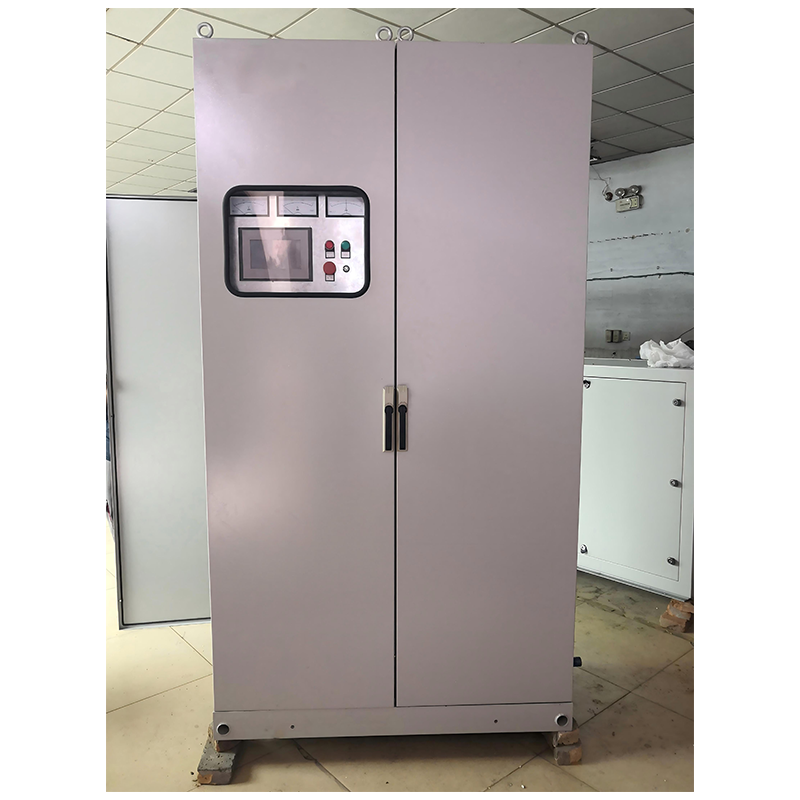
Temperature and pressure sensors are installed in specially provided lugs. Gas temperature sensors must be immersed in the flow to 1/3 of the pipeline diameter to obtain representative readings. Cables from the sensors are laid in metal corrugated sleeves to protect them from high temperatures and mechanical damage. The control cabinet is located in an area with a temperature not exceeding 40°C. The mistake at this stage is the use of conventional thermocouples instead of thermal resistances with current output, which leads to large measurement errors on long lines. - Thermal insulation and finishing.
After successfully passing hydraulic tests (pressure testing with a pressure of 1.25 from the worker), the thermal insulation is installed. First, a layer of ceramic fiber or basalt mats is applied, then a protective casing made of galvanized or stainless steel is installed. All casing joints are sealed. Particular attention is paid to the places where pipes pass through walls and ceilings - special fireproof sleeves are used here. Poor-quality insulation leads not only to energy losses, but also to personnel burns if they accidentally touch surfaces with a temperature of 300°C.
Common connection errors and their consequences
During the audit of existing facilities, we regularly identify typical mistakes made by installation organizations that do not specialize in industrial heating equipment. One of the most expensive mistakes is skimping on the quality of metal for the heat exchanger. The use of St3 grade steel instead of alloy steels (09G2S, 12Kh1MF) in high temperature zones leads to “creep” of the metal and swelling of pipes after just a year of operation. Repairing such a unit requires a complete shutdown of production and replacement of the beam, which costs several times more than the initial savings.
Another critical mistake is choosing the wrong location for installing the steam trap. Many people simply mount it at the bottom point of the body, without taking into account the hydraulic valve. As a result, exhaust gases escape through the steam trap and into the drainage system, creating the risk of carbon monoxide poisoning and the release of soot into the room. The correct scheme involves installing two sequential condensate traps with an intermediate drain into the neutralizer, where the acidic condensate is treated with an alkaline solution before being discharged into the sewer.
It is also common to ignore the requirement for a straight section of pipeline in front of the boiler. For the correct distribution of gas flow and operation of the sensors, a straight section of at least 5 pipe diameters in length before entering the boiler and 3 diameters after the exit is required. If you install the boiler immediately after the elbow or tee, the flow of gases will be uneven: one part of the bundle will be overloaded, while the other will be idle. This reduces heat transfer efficiency by 20–30% and creates local overheating zones leading to accidents.
Technical requirements and safety standards
The design and installation of heat recovery systems in Russia and the EAEU countries is regulated by strict regulatory documents. The main standard is GOST R 57376-2016 “Heat recovery boilers. General technical conditions", which defines the requirements for strength, tightness and efficiency of equipment. In addition, it is necessary to comply with the rules for the design and safe operation of pressure vessels (FNP ORD), approved by Rostekhnadzor. Failure to comply with these standards entails refusal to register the property and the imposition of large fines.
An important aspect is environmental safety. Although the waste heat boiler itself is an environmental protection equipment that reduces thermal pollution, it should not increase emissions of harmful substances. Modern models are equipped with emission monitoring systems. When burning gas with a high sulfur content, it may be necessary to install additional scrubbers or use special fuel additives. We recommend focusing on ISO 14001 standards when developing an enterprise environmental management system.
Equipment certification also plays a key role. Waste heat boilers are subject to mandatory certification in the GOST R system or declaration of compliance with the Technical Regulations of the Customs Union (TR CU 032/2013 “On the safety of equipment operating under excess pressure”). The presence of an EAC certificate confirms that the equipment has passed all the necessary tests for strength and tightness. When purchasing equipment, always ask for a copy of the certificate and factory test reports - this is your guarantee of safety and legality of operation.
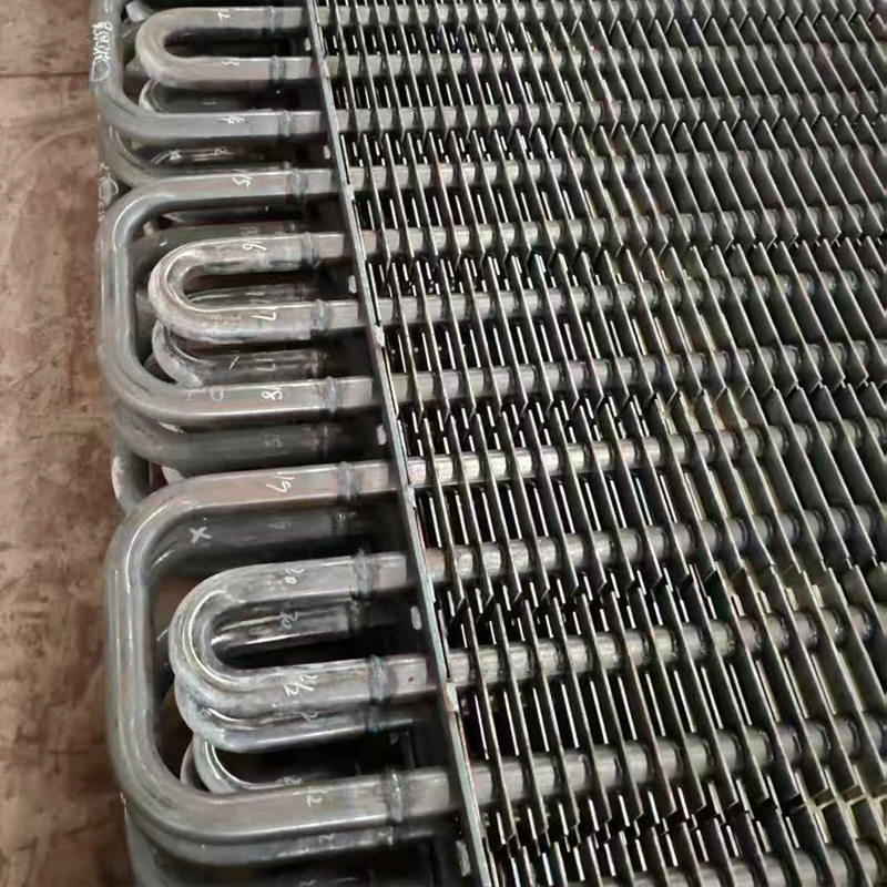
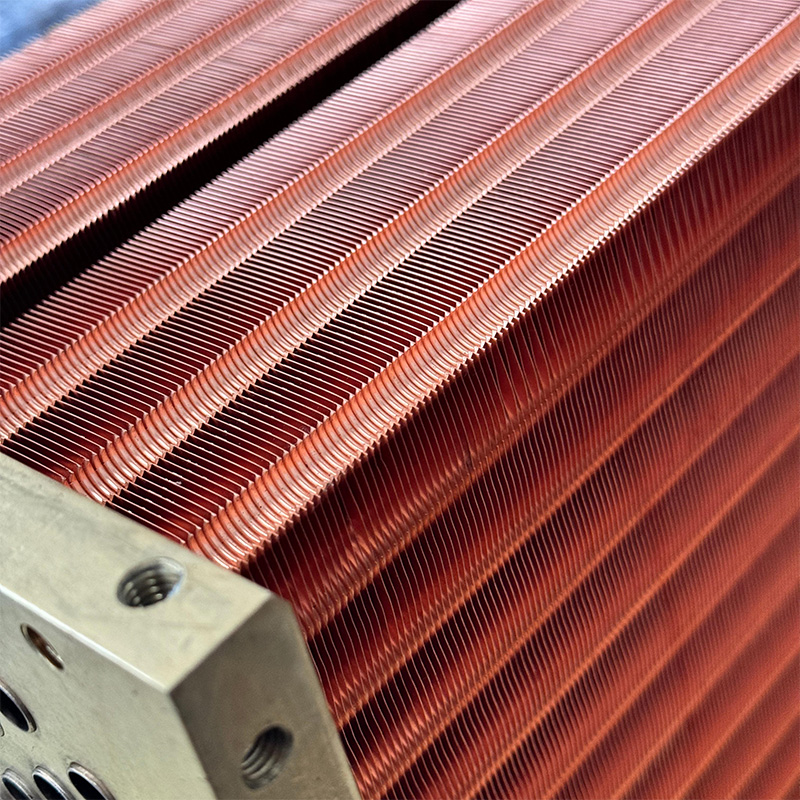
Choosing a reliable component supplier becomes a decisive factor in the longevity of the entire system. For example, a companyWuxi Kaisheng Electric Power and Petrochemical Equipment Co., Ltd.specializes in the design and production of high-quality heat exchange equipment, including waste heat boilers and their key elements. Their products, such as 316 stainless steel, N06625 nickel alloy, or C46400 marine brass corrugated tube bundles, are certified to ASME and PED international standards. The use of such materials, which have high corrosion resistance and resistance to extreme pressures and temperatures, is critical for the oil refining, chemical and energy industries, where operating conditions are most aggressive. Individual solutions from such manufacturers allow you to avoid typical problems with metal “creep” and premature failure of components.
| Parameter | GOST/TR CU requirement | Recommended value for reliability | Consequences of violation |
|---|---|---|---|
| Heat exchanger material | Suitable for operating temperature and environment | Stainless steel AISI 321 / 08Х18Н10Т | Corrosion, pipe burnout, gas leakage |
| Exhaust back pressure | No more than specified in the ICE passport | Maximum 80% of limit value | Overheating of valves, loss of power, fuel consumption +15% |
| Pipe wall temperature | Above the dew point of sulfuric acid | Minimum 150°C (with sulfur fuel) | Acid corrosion, service life reduced by 5-10 times |
| Hydraulic tests | 1.25 from working pressure | 1.5 from operating pressure (for new systems) | Pipeline rupture due to water hammer, room flooding |
| Surface insulation | Outer shell temperature ≤ 45°C | ≤ 40°C at air temperature 25°C | Heat loss up to 10%, risk of personnel burns |
Economic efficiency and payback of the project
The introduction of an exhaust gas recovery boiler is one of the fastest-paying energy saving measures in industry. A typical 1 MW diesel generator emits about 400–500 kW of thermal energy into the atmosphere via exhaust gases. By recycling even 70% of this heat, we receive an additional 300–350 kW of thermal power for free. This is equivalent to running a 350 kW electric boiler, which would consume about 400 kWh of electricity per hour. With an electricity tariff of 5 rubles per kWh, the savings are 2,000 rubles per hour.
При работе генератора в базовом режиме (8000 часов в год) годовая экономия достигает 16 миллионов рублей. Стоимость комплекта оборудования и монтажа обычно варьируется от 3 до 5 миллионов рублей в зависимости от конфигурации. Таким образом, срок окупаемости проекта составляет от 3 до 4 месяцев в зимний период и до 6–8 месяцев с учетом летнего режима, когда потребность в тепле снижается (например, только для ГВС или технологических нужд). Эти расчеты подтверждаются реальными кейсами наших клиентов в нефтегазовом секторе и металлургии.
Однако важно учитывать не только прямую экономию на топливе, но и косвенные выгоды. Снижение тепловой нагрузки на глушитель продлевает его ресурс. Уменьшение теплового загрязнения окружающей среды улучшает экологический рейтинг предприятия, что становится все более важным фактором при получении государственных контрактов и льготных кредитов. Кроме того, стабильный источник дешевого тепла позволяет расширить производство или улучшить условия труда в помещениях без капитальных затрат на новую котельную.
Frequently Asked Questions
Можно ли подключить котел-утилизатор к бензиновому двигателю?
Технически это возможно, но экономически целесообразно только для мощных стационарных установок (от 500 кВт). Температура выхлопных газов бензиновых двигателей выше (до 700–800°C), чем у дизелей, что требует применения более жаропрочных сталей и особых схем охлаждения. Кроме того, состав выхлопа отличается меньшим содержанием серы, но большим количеством несгоревших углеводородов, что требует иной настройки системы дожигания или очистки. Для небольших бензиновых генераторов стоимость оборудования редко окупается из-за малого объема утилизируемого тепла.
Что делать, если двигатель работает в переменном режиме нагрузки?
Работа в переменном режиме — самый сложный сц енарий для котла-утилизатора. При резком сбросе нагрузки температура газов падает, и возникает риск конденсации. Решение заключается в использовании инерционных аккумуляторов тепла (буферных емкостей) большого объема и быстрореагирующей автоматики. Байпасная линия должна открываться превентивно, до падения температуры ниже критической. Также рекомендуется устанавливать горелку дожига на входе в котел, которая автоматически включается при падении температуры газов, поддерживая необходимый тепловой режим за счет сжигания небольшого количества газа.
Как часто нужно чистить теплообменник от сажи?
Периодичность чистки зависит от качества топлива и режима работы двигателя. При использовании качественного дизельного топлива и работе в номинальном режиме чистка требуется не чаще одного раза в 2–3 года. Однако при работе на тяжелых видах топлива или в режиме частых пусков-остановок интервал сокращается до 6 месяцев. Загрязнение определяется по росту температуры газов на выходе при неизменной нагрузке и расходе воды. Современные системы оснащаются датчиками дифференциального давления, которые сигнализируют о необходимости обслуживания при превышении порога загрязнения.
Conclusion and recommendations for choosing a supplier
Правильно спроектированная и смонтированная схема подключения котла-утилизатора выхлопных газов превращает вредные отходы энергетики в ценный ресурс. Ключ к успеху лежит не в самом оборудовании, а в грамотной инженерной проработке проекта, учитывающей все нюансы эксплуатации конкретного двигателя. Мы убедились на собственном опыте, что попытка сэкономить на проекте или использовать типовые решения без привязки к объекту всегда приводит к дополнительным расходам на ремонт и простои.
Выбирая подрядчика для реализации такого проекта, обращайте внимание на наличие собственных инженерных расчетов и референс-лист с похожими объектами. Избегайте компаний, которые предлагают «коробочные решения» без выезда специалиста на место. Надежный партнер предоставит полный цикл услуг: от теплотехнического обоснования и 3D-моделирования обвязки до пусконаладочных работ и обучения персонала. Помните, что система будет работать десятилетиями, и цена ошибки на этапе монтажа слишком высока.
Если вы планируете модернизацию своей энергосистемы и хотите получить детальный расчет эффективности внедрения котла-утилизатора для вашего конкретного случая, наши инженеры готовы провести бесплатный аудит. Мы проанализируем режимы работы вашего оборудования и предложим оптимальную техническую схему.Contact us today, чтобы обсудить детали вашего проекта и получить коммерческое предложение с указанием сроков поставки и монтажа.
Для получения дополнительной информации о технических характеристиках нашего оборудования и примерах реализованных проектов, посетите разделпромышленные котлы-утилизаторыon our website. Там вы найдете подробные спецификации, чертежи типовых узлов и отзывы наших партнеров из различных отраслей промышленности.