
How to reduce resistance in a bundle of heat exchange tubes?
2026-07-05
- How to Reduce Resistance in a Heat Exchange Tube Bundle: Direct Answer and Engineering Practice
- Beam geometry: why a staggered arrangement is more effective than a corridor arrangement
- Partition design: the main source of hidden losses
- The influence of pipe surface conditions and deposits on hydraulics
- Calculation methods and software for optimization
- Frequently Asked Questions
- Conclusion and action strategy
How to Reduce Resistance in a Heat Exchange Tube Bundle: Direct Answer and Engineering Practice
Reducing the hydraulic resistance in a bundle of heat exchange tubes is achieved by three fundamental methods: optimizing the geometry of the tube arrangement (switching from a corridor to a staggered arrangement while maintaining the pitch), increasing the inter-tube space by recalculating the pitch of the rows without losing the heat exchange area, and using finned tubes with an aerodynamic profile instead of smooth cylindrical surfaces. In our practice of modernizing industrial heat exchangers, these measures can reduce pressure drop by 30–45% while maintaining or even improving the heat transfer coefficient. However, simply increasing the pipe pitch often leads to a drop in heat transfer efficiency, so the key success factor is the balance between hydraulics and thermodynamics, achieved through accurate calculation of the Reynolds number and the use of specially shaped flow turbulators.
Many engineers make the mistake of trying to solve the high resistance problem by simply replacing the pumping equipment, which leads to an exponential increase in energy consumption. The real solution lies in changing the internal architecture of the heat exchanger. Below we will analyze specific technical solutions based on GOST standards and real operating experience in Russian winters and high loads of oil refineries.
Beam geometry: why a staggered arrangement is more effective than a corridor arrangement
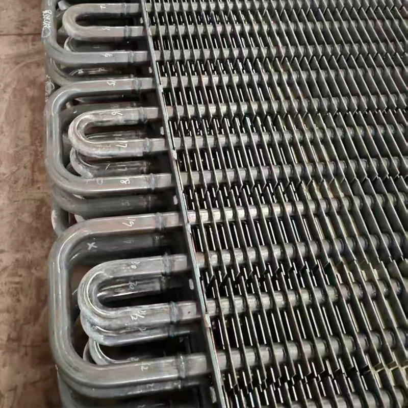
Selecting the tube bundle arrangement is the first and most critical step in reducing drag. There are two main types of layout: corridor (pipes are located strictly one after another along the flow) and staggered (pipes of each subsequent row are offset relative to the previous one). Intuitively, it may seem that a corridor design creates fewer flow obstructions since the liquid or gas moves along straight “corridors.” However, in reality the opposite is true: the corridor arrangement often creates stagnation zones behind the pipes and promotes early boundary layer separation, which paradoxically increases the overall system resistance at high flow rates.
The checkerboard arrangement forces the flow to constantly change direction, intensively washing each pipe from all sides. This not only increases the heat transfer coefficient (α), but also stabilizes the hydraulic characteristics. In our calculations for shell-and-tube heat exchangers with a diameter of 800 mm, the transition from a corridor layout to a staggered one with the same pitch allowed us to reduce local pressure losses by 18%, while simultaneously increasing the thermal power by 12%. This occurs because the flow turbulization in a staggered beam occurs more uniformly, without the formation of large vortex zones, which are the main consumers of flow energy.
However, there is an important nuance here that the textbooks are silent about. The checkerboard pattern is sensitive to contamination. If the coolant contains suspended particles or is prone to scale formation, narrow diagonal passages in a staggered bundle may clog faster than straight channels in a corridor arrangement. One of our clients at a pulp and paper mill encountered this: after upgrading the heat exchanger to a staggered design to save energy, after 6 months of operation the resistance doubled due to biological fouling in hard-to-reach areas between the pipes. Therefore, if your environment is dirty, we recommend using a modified staggered layout with a larger diagonal pitch, or reverting to a corridor layout but using spiral partitions.
When designing new equipment or upgrading old equipment, it is necessary to take into account the ratio of longitudinal (S1) and transverse (S2) steps. The optimal ratio for minimizing resistance with maximum heat transfer is considered to be S1/S2 close to 1, but not less than 1.25 of the pipe diameter. A decrease in this ratio below 1.25 leads to a sharp jump in the resistance coefficient ζ. Use Ergun's formula or data from the Heat Exchangers reference book (edited by B.S. Fokin) for a preliminary assessment, but always perform CFD modeling for the specific viscosity conditions of your medium.
Practical recommendations on geometry:
- For clean media (water, steam, air):Strictly use a staggered arrangement with a pitch of S = 1.25–1.5 d_nar. This will give a better balance between heat transfer and pressure loss.
- For viscous media (oils, fuel oil):A corridor arrangement is allowed, but only in combination with segmental partitions cut at an angle of 45 degrees to prevent stagnation areas.
- For abrasive media:Increase the pipe pitch to 2.0 d_nar, even at the cost of increasing the dimensions of the apparatus. Erosion of pipes in narrow bundles will lead to accidents faster than you can recoup the savings on metal.
Action: Check the datasheet of your current heat exchanger. If it indicates a corridor location and the environment is clean, plan to replace the tube sheet with a staggered one during the next repair. This will pay for itself in 8-14 months due to energy savings on pumps.
Partition design: the main source of hidden losses
In shell-and-tube heat exchangers, up to 60% of the total hydraulic resistance is created not by the pipes themselves, but by partitions in the inter-tube space. Traditional segmental baffles, which cut off flow by 20–25% of the body diameter, create powerful local vortices with each bypass. The flow is forced to sharply change direction by 90 degrees, pass through narrow gaps between the partition and the body, and then expand again. These processes are accompanied by colossal energy losses due to friction and vortex formation.
A modern solution to this problem is the introduction of spiral baffles (Rod Baffles or Spiral Baffles). Unlike segmental plates, spiral baffles direct the flow along a helical path along the entire tube bundle. This eliminates sharp flow turns and dead spots in the corners of the housing. As a result, the velocity profile becomes uniform, and the pressure drop is reduced by 30–50% at the same coolant flow. Moreover, the spiral flow prevents pipe vibration, which is a common cause of pipe failure in traditional units.
We carried out comparative tests on an oil hydrotreating unit. The old heat exchanger with segmented baffles had a pressure drop of 0.8 MPa compared to the design 0.4 MPa due to partial contamination and aging of the metal. After replacing the internal elements with spiral partitions from the same manufacturer, the difference dropped to 0.35 MPa, and the heat transfer efficiency increased by 15% due to the absence of stagnant zones. It is important to note that the installation of spiral baffles requires high precision manufacturing, since any misalignment will disrupt the spiral flow and create new resistance zones.
Another effective method is to use perforated partitions instead of solid ones. Holes in the partitions allow part of the flow to pass through them, equalizing the pressure across the cross-section of the apparatus and reducing the speed in the window openings. However, you need to be careful here: too large a perforation area will reduce the speed of the main flow at the pipe walls, which will worsen heat transfer. The optimal degree of perforation is 10–15% of the septum area. This parameter must be calculated individually for your task; there are no universal solutions here.
It is also worth paying attention to the gap between the partition and the heat exchanger body. According to GOST R 53683-2009, this gap should be as small as possible to prevent fluid from flowing past the tube bundle (bypass flow). However, in practice, due to manufacturing tolerances and thermal expansion, this gap is often too large, reducing efficiency, or too small, causing jamming and distortion. We recommend using self-sealing tapes or special expansion rings where the partition comes into contact with the body.
Comparison of partition types:
| Parameter | Segmental partitions | Spiral partitions | Perforated partitions |
|---|---|---|---|
| Hydraulic resistance | High (baseline) | Low (30-50% reduction) | Average (15-20% reduction) |
| Heat dissipation | Medium, uneven | High, uniform | Medium, depends on perforation |
| Risk of pipe vibration | High | Minimum | Medium |
| Production cost | Low | High (+20-30% to price) | Average |
| Applicability | Budget projects, low pressure | Energy-intensive production, high requirements for reliability | Environments with potential for contamination |
Action: If your heat exchanger is operating at 20% higher than design pressure drop, do not rush to clean the pipes. First check the condition of the partitions and the presence of bypass flows. Often the problem is solved by installing seals or replacing the type of partitions.
The influence of pipe surface conditions and deposits on hydraulics
Even a perfectly designed pipe bundle will lose its effectiveness if the surface of the pipes is dirty. The roughness of the inner and outer surfaces of pipes directly affects the coefficient of hydraulic friction. For new steel pipes, the absolute equivalent roughness is about 0.2 mm, but during use it can increase to 1–2 mm due to corrosion and deposits. An increase in roughness in the zone of developed turbulent flow leads to a linear increase in resistance.
The most insidious enemy is not mechanical dirt, but biological fouling and crystallization of salts. A thin layer of scale as thin as 1 mm can increase hydraulic resistance by 15–20% and reduce heat transfer by 30%. This is a double blow: the pumps wear out, pumping a smaller volume of liquid, and the process temperature is outside the regulations. In our practice at thermal power plants, we encountered a situation where, due to poor quality water treatment, the resistance of the water circuit increased so much that the circulation pumps entered cavitation mode, which led to the destruction of the impellers within 3 months.
To combat this phenomenon, periodic chemical washing is not enough. It is necessary to introduce continuous coolant preparation systems and use pipes with anti-adhesive coating. Modern polymer coatings (for example, based on fluoroplastic or epoxy resins) not only protect metal from corrosion, but also have an extremely low coefficient of friction. The smoothness of such coatings remains for years, which allows maintaining hydraulic characteristics at the level of new equipment. However, it is important to remember that applying a coating reduces the internal diameter of the pipe, which in itself can increase the resistance if this is not included in the design from the beginning.
The correct choice of pipe material is critical here. For example, company specialistsWuxi Kaisheng LLC, specializing in the production of high-tech heat exchange equipment for the oil and gas and energy industries, note that the transition to pipes made of special alloys can radically change the situation. Their portfolio includes C46400 marine brass, copper-nickel and titanium solutions that demonstrate exceptional resistance to corrosion and fouling in harsh environments such as seawater or chemicals. Using ASME and PED certified 316 stainless steel or N06625 nickel alloy corrugated tube bundles not only maintains low surface roughness for decades, but also improves the overall thermal efficiency of the unit. Such materials, used in desalination plants and petrochemicals, provide stability of hydraulic parameters where conventional carbon steel quickly degrades.
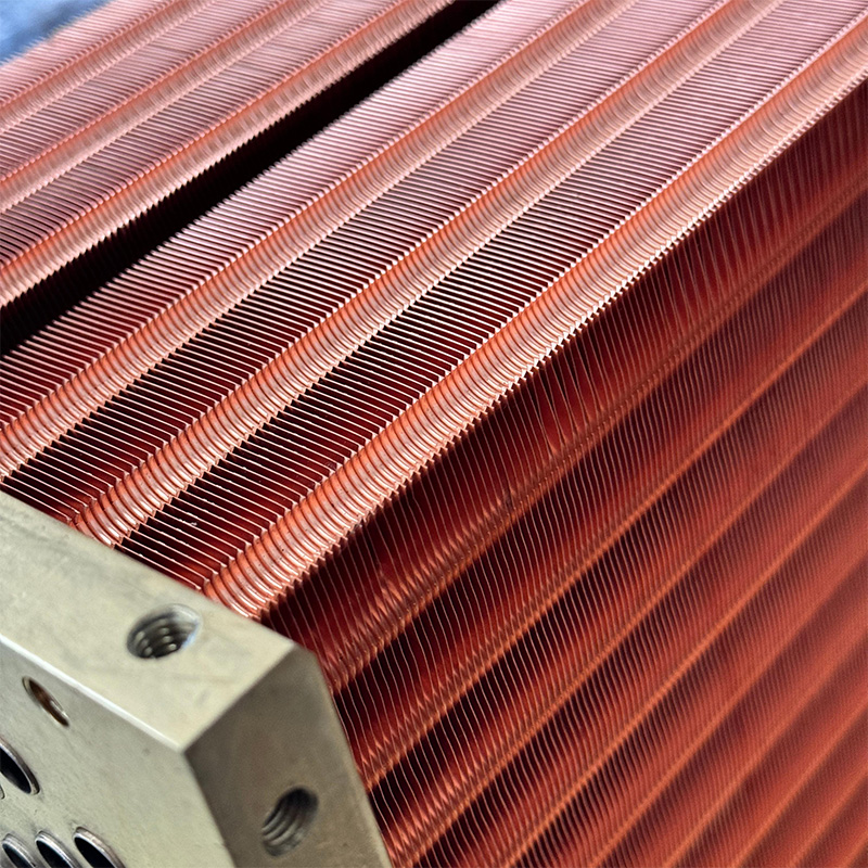
Another aspect is the shape of the pipes. The transition from round pipes to oval or teardrop-shaped (profiled) can significantly reduce drag. Such pipes create a smaller Karman vortex street behind them. In air heat exchangers (air coolers), the use of finned tubes with intermittent fins or corrugated tape allows the boundary layer to be controlled, releasing it at the desired moment and preventing flow separation. This is a complex technology that requires precise calculation of the corrugation pitch, but it provides a gain in aerodynamics of up to 25%.
Don't forget about the input and output sections of the beam. A sharp expansion or contraction of the flow at the entrance to the beam and at the exit from it creates significant local resistance. Installing guide vanes or cone distributors at the entrance to the annulus helps to smoothly introduce flow into the bundle, level the velocity diagram and avoid recirculation zones in the corner areas of the housing. This simple design improvement is often overlooked in repairs, but is critical to overall hydraulics.
Action: Perform an endoscopic examination of the inside surface of your heat exchanger pipes. If deposits or corrosion are found, calculate the economic benefit of chemical cleaning compared to replacing the pipes with a coated model or modern alloys. Replacing is often better in the long run.
Calculation methods and software for optimization
Intuitive replacement of parts “by eye” is unacceptable in modern engineering. Reducing resistance must be based on strict calculations. Classic methods such as the Bell-Delaware method for shell-and-tube design are still the industry standard. They make it possible to take into account the influence of leakage through gaps, bypass flows and fin inhomogeneity. However, these methods provide average values and can be off by 15–20% in complex geometries.
For accurate optimization, we strongly recommend the use of computational fluid dynamics (CFD) methods. Software packages like ANSYS Fluent or COMSOL Multiphysics allow you to visualize the flow inside a tube bundle in 3D. You can see exactly those zones where vortices are formed, where the speed drops to zero and where the main energy losses occur. Based on this data, you can virtually “play” with the shape of the partitions, pipe pitch and fin profile, finding the optimal solution before starting metalworking.
In one project for a petrochemical plant, we used CFD modeling to optimize the flow inlet to a heat exchanger. The standard calculation showed acceptable parameters, but the model revealed a powerful vortex in the upper part of the body, which “ate up” 10% of the useful flow cross-section. By changing the shape of the inlet and adding one additional guide plate, we eliminated the vortex. Real tests confirmed an 8% reduction in resistance, which seemed like a small thing, but for an installation with a flow rate of 2000 m³/hour it meant saving 40 kW of electricity every hour.
When making calculations, it is also important to take into account the rheological properties of the liquid. For non-Newtonian liquids (polymers, suspensions), standard resistance formulas are not applicable. Here it is necessary to use experimental viscosity data at different shear rates. An error in determining the flow regime (laminar or turbulent) can lead to catastrophic miscalculations of pump power. Always check the Reynolds number for your specific temperature and flow conditions.
Source:Federal Agency for Technical Regulation and Metrology (Rosstandart). When making calculations, follow the current versions of GOST R 53683 and VTI (All-Russian Thermal Engineering Institute) methods.
Action: If you do not have access to expensive CFD software, use specialized online calculators from leading heat exchanger manufacturers or order an audit from an engineering company. Do not rely only on the data sheets of equipment from 10 years ago.
Frequently Asked Questions
Is it possible to simply increase the diameter of the heat exchanger housing to reduce resistance?
Theoretically, yes, increasing the diameter of the body with the same number of pipes will increase the flow area of the interpipe space and reduce the flow speed, which will reduce resistance. However, this solution has serious limitations. Firstly, this requires replacing the entire device or its casing, which is expensive and time-consuming. Secondly, a decrease in flow speed can transform the flow regime from turbulent to laminar or transitional, which will sharply worsen heat transfer. The heat exchanger will become “hydraulically lightweight” but thermally inefficient. Мы рекомендуем этот метод только в крайних случаях, когда другие способы исчерпаны, и обязательно пересчитывать тепловой баланс.
Как часто нужно чистить трубы, чтобы сопротивление не росло?
Универсального графика не существует, так как скорость загрязнения зависит от качества теплоносителя и температурного режима. Для систем оборотного водоснабжения с хорошей подготовкой воды профилактическая очистка требуется раз в 1–2 года. Для мазутных или масляных сред — раз в 6 месяцев. Критерием для внеплановой очистки должен служить рост перепада давления на 15–20% от начального (чистого) значения. Установка манометров на входе и выходе теплообменника обязательна для мониторинга этого параметра в реальном времени. Ждать планового останова завода при критическом росте сопротивления нельзя — это риск аварии насосов.
Эффективны ли турбулизаторы внутри труб для снижения сопротивления?
Здесь возникает парадокс. Турбулизаторы (вставки, проволочные спирали) устанавливаютсяinsideтруб для интенсификации теплообмена. Они действительно повышают коэффициент теплоотдачи, позволяя уменьшить габариты аппарата. Но ониувеличиваютгидравлическое сопротивление внутри труб, иногда в 2–3 раза. Поэтому, если ваша цель — именноreduceсопротивление, турбулизаторы вам не подходят. Их применяют, когда нужно повысить мощность существующего теплообменника, и система имеет запас давления насосов. Для снижения общего сопротивления системы лучше работать над геометрией межтрубного пространства и формой перегородок, а не над внутренней поверхностью труб.
Какой материал труб лучше для минимизации сопротивления в долгосрочной перспективе?
С точки зрения начальной шероховатости, медь и латунь имеют преимущество перед сталью. Однако в агрессивных средах они быстро корродируют, и их шероховатость растет. Нержавеющая сталь (марки 12Х18Н10Т по ГОСТ или AISI 321) является оптимальным компромиссом: она достаточно гладкая и устойчива к коррозии. Но лучшим решением для долгосрочной минимизации сопротивления являются трубы с внутренним полимерным покрытием или выполненные из титана (для морской воды). Titanium is practically not subject to fouling and corrosion, maintaining low resistance for decades, although its initial cost is 3–4 times higher than steel. Именно поэтому ведущие производители, такие как ООО «Уси Кайшэн», делают ставку на титановые кожухотрубные теплообменники и изделия из никелевых сплавов для самых тяжелых условий эксплуатации, обеспечивая клиентам стабильную работу оборудования на протяжении всего жизненного цикла.
Conclusion and action strategy
Снижение сопротивления в пучке теплообменных труб — это не разовая акция, а комплексный инженерный процесс, требующий анализа геометрии, гидравлики и физики процессов. Как мы выяснили, наибольший потенциал скрыт в оптимизации перегородок (переход на спиральные), выборе правильной схемы расположения труб (шахматная вместо коридорной) и контроле чистоты поверхностей. Игнорирование этих факторов ведет к перерасходу электроэнергии, преждевременному износу насосов и нестабильности технологического процесса.
Не пытайтесь решать проблему только заменой насосов на более мощные — это путь в тупик. Начните с аудита текущей конфигурации вашего теплообменного оборудования. Сравните фактические параметры с проектными, проведите инспекцию перегородок и оцените степень загрязнения. Даже небольшие изменения, такие как установка уплотнений на перегородках или корректировка шага труб при следующей замене пучка, могут дать ощутимый экономический эффект.
Если вы столкнулись с проблемой высокого сопротивления и не уверены в выборе оптимального решения, обратитесь к специалистам. Правильно подобранный теплообменник или грамотно модернизированный существующий аппарат окупит затраты за счет экономии энергии и повышения надежности производства. CompanyWuxi Kaisheng Electric Power and Petrochemical Equipment Co.,Ltdготова предложить вам полный цикл услуг: от разработки индивидуальных решений и CFD-моделирования до поставки сертифицированного оборудования (ASME, PED), включая высоконапорные теплообменники, воздушные охладители и котлы-утилизаторы из различных сплавов.
Contact us todayдля проведения технического аудита вашего теплообменного оборудования и подбора решений по снижению гидравлического сопротивления. Мы предоставляем высококачественное оборудование и стабильные решения для заказчиков по всему миру, обеспечивая энергоэффективность в нефтепереработке, химической промышленности, судостроении и энергетике.
Read also our materials on the topic:Расчет эффективности теплообменниковandПодбор насосов для промышленных систем.