
Hydraulic resistance of a shell-and-tube heat exchanger: calculation 2026
2026-07-01
- Hydraulic resistance of a shell-and-tube heat exchanger: calculation 2026 and impact on operation
- Physical nature of pressure loss in the pipe space
- Hydraulics of the annulus: the role of partitions
- Effect of pollution and pollution factors on hydraulics
- Practical calculation and verification algorithm
- Сравнение методов расчета: Ручной против программного
- Стандарты и нормативная база 2026 года
- Frequently Asked Questions
- Conclusion and recommendations for choosing a supplier
Hydraulic resistance of a shell-and-tube heat exchanger: calculation 2026 and impact on operation
The pressure drop in the pipe and annulus space is a critical parameter that determines not only the choice of pumping equipment, but also the overall energy efficiency of the system in the long term. In 2026, when the cost of electricity for industrial enterprises has reached historical highs, an error in calculating the hydraulic resistance of a shell-and-tube heat exchanger can lead to cost overruns of up to 30% annually. We are seeing a trend where customers focus solely on thermal power, ignoring hydraulics, which subsequently results in the replacement of circulation pumps or a complete modernization of the piping unit. Accurate calculation requires taking into account not only the geometry of the tube bundle, but also the rheological properties of the coolant at operating temperatures, as well as roughness coefficients that change during operation.
Our engineering practice shows that standard formulas from textbooks of the 90s often give an error of up to 15-20% when working with modern viscous media or high-speed flows. In this article, we will analyze the calculation methodology relevant for projects in 2026, based on updated industry standards and real test data. You will learn how to avoid cavitation, choose the right segmental partitions and why automated calculations are sometimes inferior to manual engineering in specific conditions.
Physical nature of pressure loss in the pipe space
The resistance to fluid movement inside pipes consists of two main components: friction against the walls and local resistance. Friction depends on the flow regime (laminar or turbulent), which is determined by the Reynolds number. In most industrial heat exchangers we are dealing with a developed turbulent flow, where the coefficient of hydraulic friction weakly depends on the Reynolds number, but critically depends on the relative roughness of the pipe walls. Here lies the first trap for designers: the use of passport data for new pipes without taking into account the safety factor for pollution.
Local resistance occurs in the inlet and outlet chambers, as well as in places where the flow direction changes. If the heat exchanger is multi-pass, the liquid is forced to rotate 180 degrees several times in the distribution chambers. Each such turn generates vortex zones, dissipating the energy of the flow. The total pressure drop in the pipe space ($Delta P_{tube}$) is calculated as the sum of friction losses along the length of the pipes and losses in the local resistance of the chambers.
It is important to understand that increasing the coolant velocity to intensify heat transfer leads to a quadratic increase in hydraulic resistance. Doubling the speed quadruples the pressure drop. This is a fundamental trade-off: we get a more compact machine at the expense of high speed, but we pay for it with powerful pumps. In a 2026 environment where capital expenditures (CAPEX) for pumps are less sensitive than operating expenditures (OPEX) for electricity, the optimal speed often shifts to lower values compared to past standards.
One of our clients was faced with a situation where a heat exchanger calculated using the classical method was unable to provide the designed flow rate due to an underestimated roughness coefficient. The manufacturer used data for perfectly smooth pipes, while the actual products had micro-roughness characteristic of seamless rolled products. The result was a shortage of consumption by 18%, which led to a violation of the technological regulations of the bottling line. This case highlights the need to introduce correction factors for the actual condition of the inner surface of the pipes.
Calculation of friction losses along the length of pipes
The basic formula for determining frictional head loss is based on the Darcy-Weisbach equation. The coefficient of hydraulic friction $lambda$ is a key variable. For turbulent conditions in smooth pipes, the Blasius formula is often used, but for industrial conditions the Altschul formula, which takes into account the equivalent roughness $k_{e}$, is more accurate. The $k_{e}$ value for new steel pipes is usually taken in the range of 0.1–0.2 mm, but for pipes made of stainless steel or non-ferrous metals it can be an order of magnitude lower.
The length of the fluid path is determined by the number of strokes and the length of one pipe. It is important to remember that in multi-pass devices, the effective length increases in proportion to the number of strokes. At the same time, losses in the chambers themselves are also growing. Engineers often overlook the effect of pipe thermal expansion on flow geometry, although in high temperature applications this can significantly change clearances and therefore hydraulic performance.
For a correct calculation, it is necessary to know the dynamic viscosity of the liquid precisely at the average temperature of the flow. Viscosity is highly dependent on temperature: for water, a change of 10°C can change the viscosity by 20%, and for oils this figure changes significantly. Using average table values without reference to a specific temperature profile is a common mistake that leads to incorrect determination of the Reynolds number.
Taking into account local resistances in chambers and pipes
Losses in local resistances are calculated through coefficients $zeta$, which depend on the geometry of the entrance, exit and turns. The entrance to the pipe from the distribution chamber, the exit to the chamber, turns in the covers - each element has its own coefficient. The sum of these coefficients is multiplied by the velocity pressure. Particular attention should be paid to the inlet sections: if the entrance to the pipes does not have a smooth curve, the local resistance coefficient can increase by 1.5–2 times compared to the optimized profile.
In multi-pass heat exchangers, a significant part of the losses occurs due to turns in the intermediate chambers. The design of the partitions in the chambers must ensure uniform flow distribution throughout all passage pipes. If the flow is distributed unevenly, some of the pipes will operate with speed overload, and some will operate in stagnant zones. This not only increases the overall hydraulic resistance, but also reduces the efficiency of heat transfer due to the unevenness of the temperature field.
We recommend always adding a reserve for local resistance of 10-15% above the calculated value, especially if the heat exchanger design involves a complex piping system with a large number of shut-off valves directly in front of the device. Filters, valves and reducers installed at the inlet create additional resistance, which must be taken into account in the overall hydraulic performance of the system, and not just the heat exchanger itself.
Hydraulics of the annulus: the role of partitions
Calculating resistance in the annulus is much more complex due to the complex flow geometry. The liquid here does not move in a straight line, but in a zigzag manner, washing the pipes and encountering segmental partitions. The main sources of losses are friction during transverse flow around the tube bundle and losses due to overcoming the windows of the partitions, as well as the gaps between the partitions and the body.
Segmental partitions serve to direct the flow and prevent pipes from sagging, but they also create the main hydraulic resistance. The pitch of the baffles is an adjustable parameter: reducing the pitch increases the flow velocity in the windows and annular space, improving heat transfer, but sharply increasing the pressure drop. The optimal pitch is selected iteratively, balancing between thermal and hydraulic requirements.
The gaps between the partition and the body, as well as between pipes and holes in the partitions, create paths for liquid leaks. These leaks do not participate in useful heat exchange, but reduce the overall resistance of the device. Paradoxically, the presence of leaks can “save” the pump from overload, but the price will be a sharp drop in the efficiency of the heat exchanger. The current 2026 calculations use Bell-Delaware correction factors that take into account the effect of all types of leakage on effective flow and pressure.
In our practice, there was a case when the client insisted on a minimum spacing of partitions to maximize heat transfer in a limited space. As a result, the pressure in the inter-tube space exceeded the permissible value for the housing, which led to deformation of the partitions and vibration of the tube bundle. Vibration caused fatigue failure of the pipe rolling areas after only 8 months of operation. This example demonstrates that neglecting hydraulic calculations for the sake of thermal performance is unacceptable.
Bell-Delaware technique and modern adjustments
The Bell-Delaware method remains the gold standard for calculating shell-and-tube apparatus, but it is constantly being improved. The basic model considers an ideal tube bundle and then introduces a series of correction factors. The coefficient $J_c$ takes into account the configuration of the partitions, $J_l$ - the effect of gaps, $J_b$ - the effect of bypass flow along the body. For an accurate calculation, it is necessary to know the geometric parameters with high accuracy: body diameter, outer diameter of pipes, pipe pitch, type of pipe arrangement (triangular or square).
A triangular pipe arrangement provides a more compact layout and better heat transfer, but creates greater hydraulic resistance compared to a square arrangement. The square arrangement facilitates mechanical cleaning of the annulus, which is important for contaminated environments, but requires a larger housing diameter for the same thermal performance. The choice of pipe layout should be made at the early design stages, taking into account priorities: compactness and efficiency or maintainability and low resistance.
Modern software systems make it possible to simulate flow taking into account the three-dimensional structure, but for preliminary assessments and verification calculations, the Bell-Delaware technique remains the most transparent and understandable for the engineer. It allows you to manually track the contribution of each factor to the total resistance. We use this technique as a basic tool for verifying computer simulation results, since “black box” software can sometimes fail when given non-standard input data.
Bypass flow problem and how to solve it
Bypass flow is part of the liquid that slips between the outermost row of pipes and the wall of the housing without participating in intense heat exchange. The larger the gap between the beam and the body, the greater the bypass share. This phenomenon reduces the average flow velocity in the core and distorts the temperature profile. To combat this effect, longitudinal sealing strips are used, which bridge the gap and direct the entire flow through the tube bundle.
Installing sealing strips increases hydraulic resistance because it eliminates an easy path for fluid, but this increase is justified. It leads to an increase in speed in the working area and, as a consequence, to an intensification of heat transfer. The number and width of the slats are calculated based on the allowable gap and the required efficiency. The absence of strips in large devices can reduce efficiency by 20-30%.
When calculating resistance, it is necessary to take into account that installing strips changes the flow structure. Local velocities in areas near the slats increase, which can lead to pipe erosion or vibration. Therefore, when designing high-speed devices, the material of the slats and the method of their fastening must be selected taking into account abrasive wear. We recommend using strips made of the same material as the pipes, or wear-resistant polymers for aggressive environments.
Effect of pollution and pollution factors on hydraulics
No calculation will be complete without taking into account contamination of heat exchange surfaces. During operation, deposits form on the walls of pipes and the interpipe space: scale, corrosion products, biological fouling or polymerization of products. These deposits reduce the flow area of the channels and increase the roughness of the walls, which leads to a progressive increase in hydraulic resistance.
The pollution coefficient is initially included in the project as a reserve. However, the dynamics of sediment growth are nonlinear. In the first months of work, resistance can grow quickly, then the process stabilizes. If the system is not designed for regular cleaning or chemical flushing, the resistance may exceed the pumps' capabilities after a year or two of operation. TEMA and GOST standards provide recommendations for the selection of contamination factors depending on the type of liquid and temperature.
We encountered a case at an oil refinery where a crude oil heat exchanger lost 40% of its capacity in six months due to wax deposits. The design calculation did not take into account seasonal fluctuations in the paraffin content in the incoming oil. The solution required the installation of an online bead cleaning system (Taprogge), which allowed the hydraulic resistance to be kept within acceptable limits without stopping production. This experience has shown that for environments prone to contamination, mechanical cleaning should be included in the device concept.
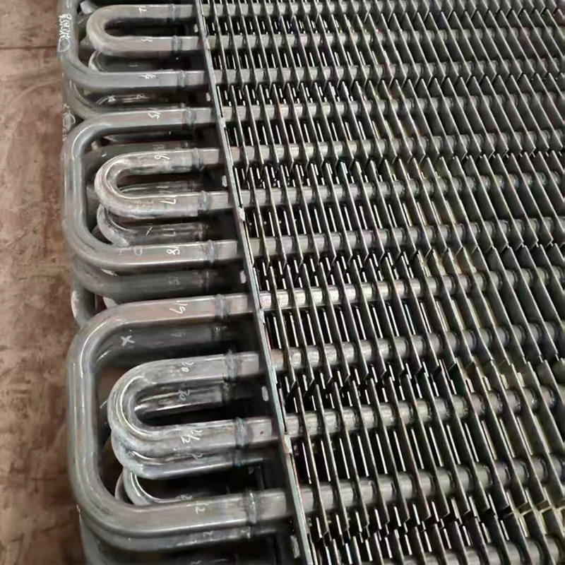
When choosing pipe materials, the tendency to fouling should also be taken into account. Smooth surfaces such as polished stainless steel or copper-nickel alloys are less susceptible to deposit adhesion compared to black steel. Although the initial cost of such pipes is higher, the reduced frequency of cleaning and stability of hydraulic parameters over the service life often make them more profitable in the long term (life cycle cost (LCC) analysis). This is why modern equipment such as 316 stainless steel corrugated tube bundles or C46400 marine brass products pay special attention to the quality of the internal surface, which directly affects the hydraulic performance.
Practical calculation and verification algorithm
For a design engineer, a clear algorithm of actions is important to minimize errors. Below is the step-by-step approach we use when auditing projects and developing new nodes. It combines analytical methods and empirical adjustments accumulated over years of practice.
- Collection of initial data and verification of their reliability.At this stage, it is necessary to obtain not only flow rates and temperatures, but also the detailed chemical composition of coolants, the presence of suspended particles, and material requirements. It is critical to clarify the permissible pressure drop from the customer. Often the customer names the value “out of his head”, without correlating it with the characteristics of the existing pumps. Our task is to request passport data of pumps or network curves. An error at this stage makes all subsequent calculations meaningless.
- Preliminary selection of device geometry.Based on the thermal load, the approximate diameter of the housing, the length of the pipes, their number and diameter are selected. The number of strokes in the pipe space is determined. The experience of similarity is used here: we look at successfully working analogues. If a device with a diameter of 600 mm was previously used for a similar task, there is no point in starting the calculation with 400 mm, unless there are strict dimensional restrictions. The type of partitions is selected (segmental, disk, spiral).
- Thermal and hydraulic calculations in conjunction.An iterative calculation is performed. Flow rates are set, heat transfer and pressure drop coefficients are calculated. If the resulting pressure exceeds the permissible one, the diameter of the apparatus is increased or the pitch of the partitions/number of strokes is changed. This process is repeated until the results converge. Важно проверять скорости на вход в патрубки: они не должны превышать 3-5 м/с для жидкостей во избежание эрозии.
- Анализ чувствительности и запасов.Проводится расчет для граничных режимов: максимальная вязкость, минимальная температура, пиковое загрязнение. Проверяется работа аппарата в режиме запуска, когда вязкость может быть максимальной. Закладывается запас по поверхности теплообмена (обычно 10-15%) и по давлению. Мы всегда проверяем, останется ли работоспособным аппарат при отказе одного из параллельно включенных насосов (если схема предусматривает резервирование).
- Верификация вибрационной стойкости.Высокие скорости потока могут вызвать вибрацию труб (вибрацию, вызванную потоком). Рассчитывается критическая скорость поперечного потока. Если рабочая скорость близка к критической, необходимо изменить шаг перегородок или установить дополнительные опоры. Игнорирование этого пункта — прямая дорога к аварии. Вибрация приводит к быстрому износу мест контакта труб с перегородками и разгерметизации.
После выполнения всех шагов формируется спецификация и чертеж общего вида. Важно, чтобы в документации были четко указаны расчетные параметры для режима “чистый аппарат” и “загрязненный аппарат”. Это даст эксплуатационному персоналу ориентиры для мониторинга состояния системы. Если манометры показывают рост дифференциального давления сверх расчетного для загрязненного состояния, это сигнал к немедленной чистке или диагностике.
Сравнение методов расчета: Ручной против программного
В современной инженерии существует дилемма: доверять ли специализированному ПО или выполнять проверку вручную? Оба подхода имеют свои преимущества и ограничения. Понимание их различий позволяет принимать взвешенные решения при проектировании ответственных узлов.
| Comparison criterion | Ручной расчет (Excel/Калькулятор) | Программное обеспечение (HTRI, Aspen EDR) |
|---|---|---|
| Скорость выполнения | Low. Требует времени на подбор коэффициентов и итерации. | High. Автоматический перебор вариантов за минуты. |
| Прозрачность логики | Full. Инженер видит каждое слагаемое формулы. | Partial. Алгоритмы скрыты внутри кода программы. |
| Учет сложных эффектов | Огран иченный. Трудно учесть все виды перетечек и вибрацию. | Wide. Включает базы данных свойств веществ и сложные модели. |
| Риск ошибки ввода | Tall. Человеческий фактор при вычислениях. | Average. Зависит от правильности введенных граничных условий. |
| Applicability | Идеально для быстрых оценок, обучения и проверки адекватности ПО. | Необходимо для финального проекта, сертификации и сложных смесей. |
Наша позиция заключается в использовании гибридного подхода. Мы используем мощное ПО для основного проектирования и оптимизации, но обязательным этапом является ручная проверка ключевых узлов (например, падения давления в самом нагруженном ходе) по упрощенным формулам. Это позволяет отловить грубые ошибки ввода данных, которые программа может “проглотить” и выдать красивый, но неверный результат. Программа не заменяет мышление инженера, она лишь усиливает его возможности.
Стоимость лицензий на профессиональное ПО высока, и для небольших инжиниринговых бюро это может быть барьером. В таких случаях качественные Excel-таблицы с макросами, разработанные на базе методик TEMA, могут стать достойной альтернативой для аппаратов стандартного назначения. Главное — регулярное обновление баз данных свойств теплоносителей в таких таблицах.
Стандарты и нормативная база 2026 года
При проектировании теплообменного оборудования необходимо руководствоваться актуальными стандартами. В международном контексте основным документом является стандарт TEMA (Tubular Exchanger Manufacturers Association), который классифицирует аппараты по классам надежности (R, B, C) и содержит детальные методики расчета. Для рынка России и ЕАЭС применяются ГОСТы, гармонизированные с международными нормами, но имеющие свою специфику.
ГОСТ Р 53683-2009 (аналог ISO 16812) регламентирует требования к кожухотрубным теплообменникам для нефтегазовой отрасли. Важным аспектом является соответствие требованиям Технического Регламента Таможенного Союза ТР ТС 032/2013 “О безопасности оборудования, работающего под избыточным давлением”. Этот регламент определяет процедуры оценки соответствия, которые обязательны для ввода оборудования в эксплуатацию на территории ЕАЭС.
В 2026 году ужесточились требования к энергоэффективности промышленного оборудования. Новые директивы требуют обоснования выбора оборудования с точки зрения минимизации потребления энергии на протяжении всего жизненного цикла. Это означает, что при тендерных закупках преимущество будут получать аппараты с оптимизированным гидравлическим сопротивлением, даже если их начальная стоимость немного выше. Сертификат энергоэффективности становится таким же важным документом, как и паспорт качества.
Мы рекомендуем при заказе оборудования требовать от поставщика предоставления расчетного листа (технический паспорт), где явно прописаны методы расчета и использованные стандарты. Это защищает заказчика от использования устаревших методик и позволяет провести независимую экспертизу проекта. Наличие сертификата ISO 9001, а также соответствие международным стандартам PED и ASME у производителя также являются маркерами качества процессов проектирования и контроля, гарантируя надежность оборудования даже в экстремальных условиях.
Frequently Asked Questions
Как уменьшить гидравлическое сопротивление без замены теплообменника?
Существует несколько способов снижения сопротивления в действующем оборудовании. Наиболее радикальный — удаление части сегментных перегородок, что увеличит шаг и снизит скорость потока, но ухудшит теплообмен. Более щадящий метод — химическая или гидроударная очистка трубного пучка от отложений, что восстановит проходное сечение. Также можно рассмотреть замену рабочего колеса насоса на модель с другой характеристикой, если снижение давления приведет к недопустимому падению расхода. В некоторых случаях помогает установка антифрикционных покрытий внутрь труб, хотя это требует демонтажа аппарата.
Какая допустимая скорость теплоносителя в трубах?
Для воды и водных растворов рекомендуемая скорость составляет 1.0–2.5 м/с. Снижение скорости ниже 1.0 м/с способствует осаждению шлама и биообрастанию. Превышение 3.0 м/с резко повышает риск эрозионного износа, особенно если в воде есть твердые частицы, и увеличивает шум. Для вязких жидкостей (масла) скорости могут быть ниже (0.5–1.5 м/с) из-за высокого числа Рейнольдса даже при малых скоростях. Конкретное значение всегда определяется балансом между коэффициентом загрязнения и допустимым перепадом давления.
Почему растет давление в теплообменнике со временем?
Рост перепада давления — верный признак загрязнения внутренних полостей. Это может быть накипь (карбонаты кальция), ржавчина, биологическая слизь или полимеризация органики. Реже причиной является механическое повреждение перегородок, которое меняет траекторию потока и создает локальные завихрения. Если давление растет скачкообразно, возможно попадание постороннего предмета в патрубок. Плановый мониторинг дифференциального давления позволяет прогнозировать время следующей чистки и избегать аварийных остановок.
Conclusion and recommendations for choosing a supplier
Гидравлическое сопротивление кожухотрубного теплообменника — это не просто цифра в расчетном листе, а параметр, напрямую влияющий на надежность и экономику вашего производства. Ошибки в расчетах стоят дорого: от сгоревших насосов до срыва технологических процессов. В 2026 году подход к проектированию должен быть комплексным, учитывающим не только тепловую мощность, но и гидравлическую стабильность, ремонтопригодность и энергоэффективность.
Мы рекомендуем не экономить на этапе инженерных изысканий. Качественный расчет, выполненный с использованием современных методик и проверенный экспертом, окупается многократно в процессе эксплуатации. При выборе оборудования обращайте внимание на готовность производителя предоставить детальные расчеты, адаптированные под ваши конкретные условия, а не просто предложить типовое решение из каталога.
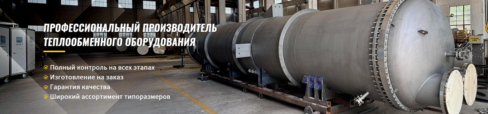
Выбор надежного партнера играет решающую роль в успехе проекта. CompanyWuxi Kaisheng Electric Power and Petrochemical Equipment Co., Ltd.специализируется на разработке и производстве высокоэффективных теплообменных решений для самых сложных отраслей промышленности. Наш портфель включает титановые кожухотрубные теплообменники, аппараты высокого давления по стандарту ASME, а также уникальные трубные пучки из гофрированной нержавеющей стали 316, морской латуни C46400 и жаропрочных никелевых сплавов N06625. Мы также производим воздушные охладители, котлы-утилизаторы и комплектующие, такие как трубные решетки из стали 321 и сплавов C70600.
Продукция «Уси Кайшэн» изготавливается из углеродистой, нержавеющей, легированной стали, титана, меди и никелевых сплавов, что обеспечивает исключительную коррозионную стойкость и способность работать под высоким давлением и при экстремальных температурах. Все изделия сертифицированы по строгим международным стандартам PED и ASME. Благодаря собственному инженерному отделу, мы проводим точные гидравлические расчеты для каждого заказа, гарантируя оптимальное соотношение тепловой эффективности и падения давления. Наши решения широко применяются в нефтепереработке, химической промышленности, опреснении морской воды и судостроении, помогая клиентам по всему миру достигать максимальной энергоэффективности.
Если вы столкнулись с проблемой подбора теплообменника или хотите провести аудит существующего оборудования на предмет энергоэффективности, свяжитесь с нашими специалистами. Мы готовы выполнить предварительный расчет и предложить оптимальную конфигурацию аппарата, которая сэкономит ваши средства на электричестве и обслуживании.
Contact us todayдля получения консультации и коммерческого предложения от команды профессионалов. We also recommend that you check out ourкаталогом кожухотрубных теплообменников, где представлены модели различных классов исполнения, созданные с учетом требований 2026 года.