
Heat recovery boiler: piping diagrams
2026-10-07
- Heat recovery boiler: piping diagrams and key design principles
- Typical piping schemes: analysis of effectiveness and scope of application
- Technical requirements for strapping components and materials
- The role of high-quality equipment and materials in system reliability
- Installation and commissioning algorithm
- Cost-effectiveness and return on investment
- Compliance with Standards and Regulatory Requirements
- Frequently Asked Questions
- Conclusion and recommendations for action
Heat recovery boiler: piping diagrams and key design principles
The correct piping scheme for a hot water waste heat boiler is the foundation that determines 80% of the success of the entire energy-saving system. In our engineering practice, we have repeatedly encountered situations where expensive equipment failed in the first six months of operation solely due to errors in the hydraulic coupling of circuits. Subjectводогрейный котел утилизатор: схемы обвязкиrequires a detailed analysis of not only theoretical aspects, but also real installation cases, where ignoring the dynamics of flows led to pump cavitation or thermal shock of the heat exchanger. We will look at specific piping configurations that ensure stable operation under varying heat loads from industrial furnaces.
Let's get straight to the point: there is no universal scheme, but there are strict rules, the violation of which is unacceptable. If the flue gas temperature fluctuates by more than 50°C over an hour, you need a circuit with a flue gas bypass and a buffer tank in the water circuit. Ignoring this requirement leads to condensation of aggressive acids on the pipe walls when the temperature drops below the dew point. Below we take a closer look at the three main piping architectures tested in the metals and chemicals industries, and explain why standard solutions are often ineffective for specific production runs.
Critical errors when choosing pipeline configurations
One of our clients, a large glass manufacturer, lost almost 15% of the plant's thermal output in its first year of operation. The reason lay not in the boiler itself, but in the way it was implementedheat recovery boiler piping diagram. The contractor's engineers used a classic series pump connection scheme without taking into account the hydraulic resistance of long sections of the chimney. This led to the fact that during peak loads, water circulation slowed down, causing local overheating and boiling of the coolant in areas of maximum heat removal. We strongly recommend avoiding such simplifications, especially if the length of the route from the heat source to the consumer exceeds 50 meters.
Another common problem is the lack of protection against low-temperature corrosion. Many projects involve supplying cold return water directly to an area of intense heat exchange. When the pipe wall temperature drops below 130–140°C (depending on the composition of the fuel being burned), sulfur condensate begins to form. This process destroys steel at a rate of up to 2 mm per year. Proper piping should include a mixing unit, which ensures that the temperature of the water entering the boiler will never be below a critical threshold, even at the time of starting the system in winter. This is not just a recommendation, but a requirement dictated by the physicochemical properties of combustion products.
Typical piping schemes: analysis of effectiveness and scope of application
The choice of a specific configuration depends on the load profile of the enterprise. We have identified three main types of schemes, each of which solves specific problems. Understanding their differences allows you to avoid overpaying for redundant equipment or, conversely, the risks of an emergency shutdown of production.
Scheme No. 1: Direct connection with simplicity as a priority
This configuration is used where the heat source operates in a stable manner 24/7 and hot water consumption is uniform. Hereheat recovery boileris connected in series to the return pipeline of the heating system or technological process. The pump creates pressure by pushing the coolant through the heat exchanger.
- Benefits:Minimum number of shut-off valves, low installation cost, ease of automation.
- Disadvantages:Complete dependence on the stability of the heat source. When the stove stops, circulation stops, which can be dangerous in winter. Inability to regulate the outlet temperature regardless of the furnace load.
- Where to use:Small boiler houses at thermal power plants, drying chambers with a continuous cycle, where the operating schedule coincides with the heating schedule of the workshops.
It is important to note: in this scheme, it is necessary to have a check valve and a membrane-type expansion tank designed for the full volume of the system. We have seen cases where savings on a tank with a volume of only 50 liters resulted in a rupture of the weakest link in the system - usually this is a weld on the boiler itself.
Diagram No. 2: Hydraulic separator (Gidrosrelka) for unstable loads
This is the most reliable option for modern industries, where the operation of furnaces is cyclical, and heat consumers have different temperature schedules. The hydraulic separator breaks the connection between the boiler circuit and the consumer circuit, allowing each pump to operate in its optimal mode. Schemeводогрейный котел утилизатор: схемы обвязкиusing a hydraulic arrow becomes the de facto standard for large industrial facilities.
The principle of operation is simple: the boiler circuit drives water through the heat exchanger at a constant flow rate, providing effective heat removal and protection against overheating. The consumer circuit takes as much energy as is needed at the moment. Excess heat is accumulated or discharged through a bypass. The main advantage is the ability to connect several independent consumers (heating, hot water, technology) with different temperatures.
We recommend this scheme if the difference in circuit flows exceeds 20%. For example, if the boiler pumps 50 m³/h, but the heating system only requires 10 m³/h at night, a direct connection will result in water hammer and noise. The hydraulic arrow dampens these differences. However, there is a nuance: the diameter of the separator body must be calculated strictly according to the vertical flow velocity (no more than 0.1–0.2 m/s), otherwise it will turn into a regular tee and will not fulfill its function.
Scheme No. 3: Mixed system with flue gas bypass
For high power units running on high sulfur fuel, wall temperature control is critical. A scheme is used here where part of the flue gases passes past the heat exchanger through an adjustable gate. This allows you to maintain the flue gas temperature above the dew point, sacrificing part of the efficiency for the sake of equipment longevity.
In a water circuit with this scheme, a two-circuit system is often used: the primary circuit is heated to a high temperature (for example, 95°C) and goes to the heat accumulator, and the secondary circuit mixes hot water with return water through a three-way valve, supplying the network with the required temperature. This approach requires complex automation, but pays off by increasing the service life of the boiler metal by 2–3 times.
Technical requirements for strapping components and materials
Even an ideal circuit will fail if the components are chosen incorrectly. In the sectionводогрейный котел утилизатор: схемы обвязкиWe often see how customers save on fittings without understanding the operating conditions. The temperature in the heat exchanger circuit can reach 115–150°C at a pressure of up to 0.6 MPa, and even higher in emergency modes. Regular household fittings will not work here.
Selection of pumping equipment
Circulation pumps must be designed for high temperatures (up to +140°C). Standard pumps with graphite seals can leak even at +90°C in long-term operation. We use pumps with mechanical seals made of silicon carbide or ceramic. An important parameter is headroom. The resistance of the heat exchanger of the heat exchanger is high due to the developed fin surface. The margin should be at least 15–20% of the calculated value.
Pumps are installed only on the supply or return pipeline, ensuring a straight section of pipe in front of the suction pipe (minimum 5 pipe diameters). This prevents turbulence and cavitation. In our practice, there was a case when a pump installed immediately after a 90° elbow failed after 3 months due to erosion of the impeller by steam bubbles.
Shut-off and control valves
To shut off the boiler, full bore ball valves with a reinforced body are required. The use of cast iron fittings is prohibited at temperatures above +120°C due to the risk of brittle fracture. Steel or ductile iron only. To regulate the temperature, three-way mixing valves with electric drives that have the function of returning to a safe position in the event of a power failure are required.
Particular attention is paid to the security group. It should include a safety valve set to a pressure 10% higher than the operating pressure, but not higher than the maximum permissible for the boiler. Pressure gauges must have dampers (siphon tubes) that protect the mechanism from pressure pulsations and overheating.
Thermal insulation and expansion compensation
Piping pipelines operate in extreme temperature conditions. The linear expansion of a 10 meter long steel pipe when heated from 20°C to 120°C is about 12 mm. If expansion joints (U-shaped or bellows) are not installed, this force will break the flange connections or deform the boiler pipes. We require expansion joints to be installed on all straight sections longer than 6 metres.
The insulation must withstand temperatures up to 200°C with a margin. The use of foamed polyethylene is unacceptable - it melts. Only high-density stone wool or special grades of foam rubber with aluminum coating. Heat losses from uninsulated areas of the piping can reach 10–15% of the generated energy, which negates the economic effect of installing a heat exchanger.
The role of high-quality equipment and materials in system reliability
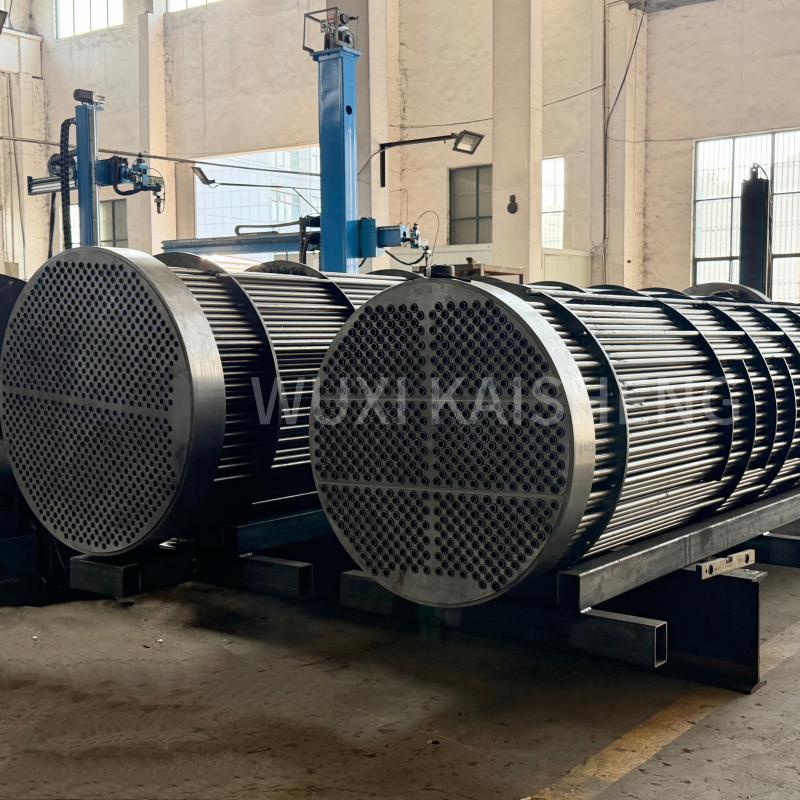
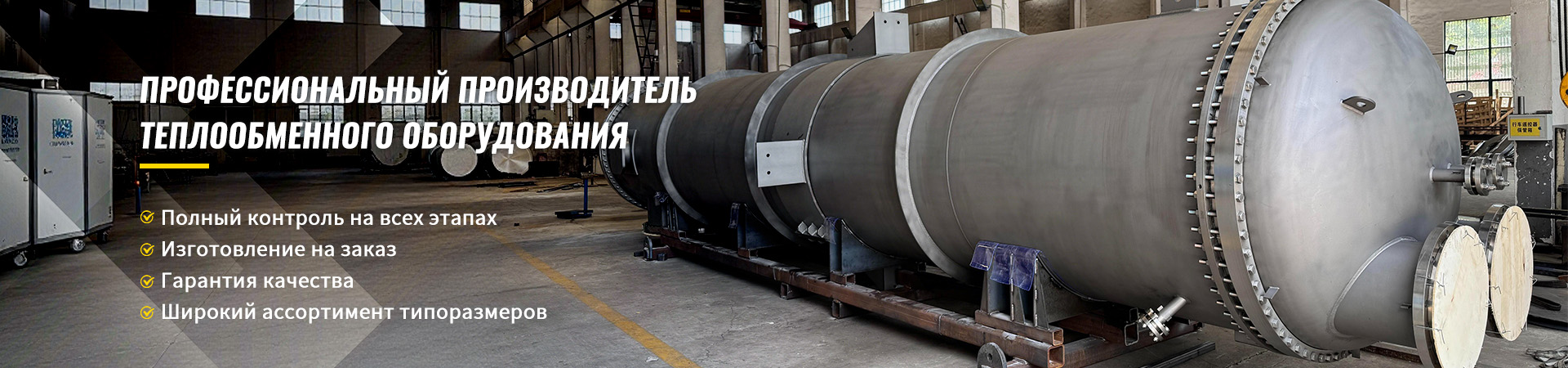
The effectiveness of any of the considered schemes directly depends on the quality of the main equipment and materials of heat exchange surfaces. This is where specialist manufacturers such asWuxi Kaisheng Electric Power and Petrochemical Equipment Co., Ltd.. The company specializes in the development and production of highly efficient heat exchange solutions, including waste heat boilers, capable of operating in the most aggressive environments of the oil refining, petrochemical and energy industries.
Experience shows that the use of standard materials often leads to premature failure of components. Unlike mass solutions, Wuxi Kaisheng products are made from specialized alloys: titanium, 316 and 321 stainless steel, C46400 marine brass, C70600 copper-nickel alloys and N06625 heat-resistant nickel alloys. This is critical to prevent corrosion when exposed to seawater or sulfur dioxide gases. Their corrugated tube bundles and shell-and-tube heat exchangers, certified to stringent international ASME and PED standards, provide not only high thermal efficiency, but also resistance to extreme pressures and temperatures, ensuring a long life for the entire heat recovery system.
Installation and commissioning algorithm
Installing a system is not just assembling pipes according to a drawing. This is a process that requires a strict sequence of actions. Violation of technology at any stage leads to problems that are difficult to eliminate after the fact. Below is a step-by-step algorithm that we use at our facilities.
- Substrate preparation and positioning.The waste heat boiler has a significant weight, especially with water inside. The foundation must be designed for static and dynamic loads. Before installation, the horizontality of the site is checked with a laser level. A misalignment of more than 2 mm per meter of length can lead to uneven stress distribution in the housing.Common mistake:ignoring vibration isolation pads under the boiler supports, which transmits vibration from the gas flow to building structures.
- Circuit assembly and welding work.All joints are made by argon-arc welding to ensure tightness and smoothness of the internal walls. Seams are subjected to visual inspection and, at pressures above 0.4 MPa, radiographic inspection. There should be no scale, slag or rags left inside the pipes. Before final cooking, blowing with compressed air is carried out.Attention:Do not allow welding splashes to come into contact with the boiler body - this creates pockets of future corrosion.
- Hydraulic tests (pressure testing).The system is filled with water and subjected to pressure exceeding the working pressure by 1.25–1.5 times (according to GOST or internal plant regulations). Pressure exposure is at least 10 minutes. All seams, flanges and gland seals are inspected. Even microscopic leakage is unacceptable. At this stage, hidden installation defects are identified.
- Chemical flushing and filling.Before the first start-up, the system must be flushed from residual grease, rust and installation debris. Process water with the addition of corrosion inhibitors is used. Filling is done from the bottom up to avoid the formation of air pockets. All air vents must be open until water appears.
- Automation setup and test run.The operating logic of temperature and pressure sensors is checked. The pumps are started manually to check the direction of rotation. The system is then switched to automatic mode. The first heating is carried out smoothly, at a speed of no more than 30°C per hour, in order to relieve thermal stress from the metal. The operation of the safety group and expansion tank is monitored.
After successfully completing the 72-hour test period, a commissioning certificate is signed. Only after this the system is considered ready for industrial operation.
Cost-effectiveness and return on investment
The implementation of the correct strapping scheme directly affects the ROI of the project. Let's look at the numbers. Installing a 1 MW hot water waste heat boiler allows saving approximately 80–90 thousand cubic meters of natural gas per year (with 8,000 hours of operation). At current energy prices in the Russian Federation and the CIS, this is a significant amount.
However, if the piping scheme is ineffective and the efficiency of the system drops by 10% due to poor circulation or heat loss, the payback period increases by 1.5–2 years. Moreover, repairing a boiler after an accident due to improper piping can cost up to 30% of the price of new equipment. Therefore, investments in a competent project and high-quality materials pay off many times over due to uninterrupted operation.
We audited the system at a cement plant, where the introduction of a circuit with a hydraulic separator and high-quality thermal insulation allowed us to increase the thermal energy utilization factor from 0.65 to 0.82. This provided an additional economic effect of 12 million rubles per year only due to more complete heat removal from the exhaust gases.
Compliance with Standards and Regulatory Requirements
The design and installation of heat recovery systems in Russia and the EAEU countries is regulated by strict standards. Main documents to rely on:
- FNP "Industrial safety rules for hazardous production facilities that use equipment operating under excess pressure."This document defines the requirements for boiler registration, personnel qualifications and the frequency of inspections.
- GOST R 57376-2017 “Water heating boilers. General technical conditions".Sets reliability, safety parameters and test methods.
- SP 89.13330.2016 “Boiler installations”.Contains requirements for placement, piping and automation of boiler rooms.
Ignoring these standards is not only illegal, but also dangerous. Insurance companies may refuse to pay if an insured event occurs if the project is found to be non-compliant with standards. In addition, the equipment must have a certificate of conformity with TR CU 032/2013 “On the safety of equipment operating under excess pressure.” The presence of the EAC marking on the boiler and main piping components is mandatory for legal operation.
Frequently Asked Questions
What is the minimum return water temperature to prevent corrosion?
For most types of industrial fuel (fuel oil, coal, gas with sulfur impurities), the minimum metal wall temperature should be 130–140°C. To ensure this, the temperature of the return water entering the waste heat boiler should not fall below 70–80°C, depending on the design of the heat exchanger. Если ваша система отопления требует более низкой температуры (например, теплые полы 40°C), использование схемы с прямым возвратом категорически запрещено. Необходимо применять смесительный узел или промежуточный теплообменник, чтобы разделить контуры и защитить утилизатор от низкотемперностной агрессии.
Можно ли использовать антифриз в качестве теплоносителя?
Технически это возможно, но экономически и эксплуатационно нецелесообразно для мощных промышленных утилизаторов. Антифризы имеют меньшую теплоемкость (на 15–20% ниже воды), что требует увеличения расхода насосов и диаметров труб. Они склонны к старению и потере свойств при высоких температурах (выше 100–110°C многие гликоли начинают разлагаться). Кроме того, вязкость антифриза выше, что увеличивает гидравлическое сопротивление. Мы рекомендуем использовать воду с пакетом антикоррозионных присадок. В случае риска замерзания в аварийных ситуациях лучше предусмотреть систему аварийного слива или электроподогрев узлов, чем заливать всю систему химией.
Как часто нужно чистить теплообменник котла-утилизатора?
Периодичность чистки зависит от запыленности дымовых газов и наличия липких фракций. Для чистых газов (например, от газовых турбин) достаточно ежегодного визуального осмотра и чистки раз в 2–3 года. Для печей обжига, где есть пыль и конденсат, чистка требуется каждые 3–6 месяцев. Главный индикатор необходимости чистки — рост температуры уходящих газов при неизменной нагрузке. Если дельта температур выросла на 10–15°C сверх проектного значения, значит, поверхность загрязнена. Игнорирование чистки приводит к росту сопротивления тракта и падению КПД установки.
Conclusion and recommendations for action
Разработка системы, в которой задействованводогрейный котел утилизатор: схемы обвязкииграют решающую роль, требует профессионального подхода и учета множества переменных. Нельзя просто скопировать решение с другого объекта — каждый источник тепла уникален. Ошибки в проекте стоят дорого, а их исправление в ходе эксплуатации часто невозможно без остановки производства.
Если вы планируете модернизацию своей котельной или установку нового оборудования утилизации тепла, не рискуйте, полагаясь на типовые решения. Доверьте расчет гидравлики и подбор оборудования специалистам, имеющим реальный опыт работы с промышленными утилизаторами. Правильно спроектированная система станет надежным источником дешевой энергии для вашего предприятия на десятилетия.
Мы готовы провести аудит вашей текущей системы или разработать индивидуальный проект обвязки с учетом всех технологических нюансов.Contact us todayдля получения консультации и расчета потенциальной экономии. Также рекомендуем ознакомиться с нашим материалом овыборе промышленных котловдля комплексного понимания вопроса энергоэффективности.