
U-shaped finned tube with longitudinal ribs
2026-10-04
- Technical characteristics and design features of U-shaped finned tube
- Industrial Application: Solving Heat Transfer Problems in Challenging Environments
- Selection factors and comparison with alternative fin types
- Manufacturing standards and product quality control
- Логистика, монтаж и типичные ошибки при установке
- Коммерческие условия поставки и сотрудничество с производителем
- Frequently asked questions (FAQ)
Technical characteristics and design features of U-shaped finned tube
The U-shaped finned tube with longitudinal fins is a critical element of heat transfer equipment where the heat transfer efficiency is directly dependent on the surface geometry. In our engineering practice, we have observed cases where ignoring the exact parameters of the fin pitch led to a decrease in the efficiency of the installation by 18–22% already in the first year of operation. The design of such pipes is based on the principle of increasing the contact area between the coolant inside the pipe and the working environment outside due to continuous metal lamellas welded or rolled along the entire length of the straight section.
The main difference between this configuration and spiral fins is the aerodynamic properties of the flow. Longitudinal ribs create less resistance to the movement of gases or liquids, which allows their use in systems with limited discharge pressure of fans or pumps. The standard models we supply to refineries have main tube diameters ranging from 25mm to 76mm, with fin heights ranging from 3mm to 15mm. The fin thickness is usually 0.8–1.2 mm, which provides the necessary balance between mechanical strength and thermal inertia.
The material used plays a decisive role in the durability of the assembly. For aggressive environments, such as flue gases with a high sulfur content, we recommend using steel grade 09G2S or stainless alloys AISI 304/316L. In conditions of extremely low temperatures, characteristic of the northern regions of Russia, the use of carbon steel without special treatment is unacceptable due to the risk of cold brittleness. Each production cycle is accompanied by incoming metal inspection according to quality certificates corresponding to GOST 1050 or international analogues ASTM A179.
The process of forming the fins is carried out by high-frequency welding or contact welding, which guarantees the absence of air gaps between the base and the fins. The presence of even a microscopic gap creates thermal resistance, which can neutralize the entire effect of increasing the surface area. Our laboratories carry out selective metallographic analysis of the seam on every fifth sample of the batch to eliminate the risk of ribs peeling under the influence of thermal cycling. This requirement is especially relevant for installations operating in frequent starts and stops.
The geometry of the U-bend requires special attention when calculating the stresses in the material. The bending radius should not be less than three outer diameters of the pipe to avoid thinning of the wall in the area of greatest tension. Violation of this rule often leads to depressurization of the circuit under operating pressure above 2.5 MPa. We record all bending parameters in the product passport, including the angle of deviation of the plane of the U-shaped part, which should not exceed ±2 degrees to ensure correct installation into the heat exchanger tube sheet.
The choice of a specific pipe modification depends on the required heat transfer coefficient and permissible pressure losses in the system. Engineers often make the mistake of selecting the maximum fin height without considering the flow rate, which results in the interfin space becoming clogged with soot or dust. The optimal ratio of fin pitch to their height should be in the range of 1.5–2.5 for gaseous media and 3.0–4.0 for viscous liquids. Before approving the project specification, it is necessary to carry out a hydraulic calculation to confirm the performance of the selected configuration under real operating conditions.
Industrial Application: Solving Heat Transfer Problems in Challenging Environments
The operating efficiency of industrial heaters and coolers directly depends on the correct selection of the type of fins for a specific task. U-shaped finned tube with longitudinal ribs has found wide application in situations where traditional smooth tubes cannot cope with the required thermal load with limited dimensions of the apparatus. Let's look at two real cases from our practice that demonstrate the quantitative benefits of using this technology in different industries.
The first case concerns the modernization of an air heater at a cement plant in the Ural region. The customer was faced with the problem of insufficient heating of the secondary air, the temperature of which was only 140°C instead of the design 280°C. This led to unstable combustion in the furnace and excessive fuel consumption by 12%. Replacing old smooth pipes with blocks of U-shaped pipes with longitudinal fins 10 mm high made it possible to increase the heat transfer area by 6.5 times without changing the dimensions of the apparatus body. After launching the updated system, the air temperature stabilized at 275–285°C, and natural gas consumption decreased by 9.4% per ton of clinker.
The second example relates to the chemical industry, where it was necessary to cool the process gas before compression. The original system based on plate heat exchangers constantly failed due to contamination of the channels with polymer deposits. Switching to a shell-and-tube design using stainless steel U-shaped finned tubes solved the problem of fouling. Longitudinal ribs created a laminar flow, which prevented heavy fractions from settling on the heating surface. As a result, the intervals between preventive cleanings increased from 45 days to 180 days, and the productivity of the compressor station increased by 15% due to a stable inlet gas temperature.
A key success factor in both cases was the correct consideration of the characteristics of the work environment. In the case of the cement plant, it was important to ensure resistance to abrasive wear by dust particles, so we used pipes with a thickened rib base. For chemical production, the priority was corrosion resistance and the ability to clean mechanically. There is no universal solution: what works perfectly for heating air can be disastrous for condensation of acid vapors.
Calculation of the economic efficiency of implementing such systems shows a payback period of 8 to 14 months, depending on the energy tariffs of the enterprise. Reducing fuel or electricity consumption for own needs is the main driver of return on investment. In addition, reducing the size of heat exchange equipment makes it possible to reduce capital costs for the construction of new workshops or reconstruction of existing areas. The compactness of U-shaped blocks makes it possible to fit them into the cramped conditions of existing production lines without dismantling the supporting structures.
However, there are restrictions on use. The use of longitudinal fins is not recommended in environments with a high tendency for salt crystallization on the surface of the pipes, since the narrow channels between the fins can quickly become clogged. The use of such pipes in systems with high amplitude pulsating flow, which can cause fatigue failure of the fin weld, should also be avoided. Before making a decision to replace equipment, it is necessary to conduct an audit of the current process parameters and obtain advice from heating engineering specialists.
The successful implementation of such projects requires close interaction between the customer and the manufacturer at the design stage. Providing accurate data on gas composition, presence of impurities, plant operating schedule and required temperature conditions allows engineers to select the optimal pipe configuration. Errors at the initial data collection stage inevitably lead to ineffective system operation in the future, which is confirmed by numerous cases of premature equipment failure due to the wrong choice of materials or geometry.
Selection factors and comparison with alternative fin types
When designing heat transfer equipment, engineers are often faced with a choice between different types of fins. Understanding the differences between U-tube with longitudinal fins and other common options such as spiral fins or spiked tubes is key to the reliability of the entire system. Below is a detailed comparison of key parameters to help you make an informed decision.
| Comparison parameter | Longitudinal fins (U-tube) | Spiral fins | Spiked pipe |
|---|---|---|---|
| Aerodynamic drag | Low. The flow moves parallel to the fins, minimizing turbulence. | Medium/High. The spiral twists the flow, creating additional resistance. | High. The chaotic arrangement of the spikes greatly slows down the flow. |
| Heat dissipation efficiency | High at high flow rates. Uniform temperature distribution. | Very high due to flow turbulence even at low speeds. | Maximum surface area, but uneven heating. |
| Tendency to pollute | Low. Self-cleaning effect at sufficient flow rate. | Average. Dirt may get stuck in the spiral coils. | High. The space between the spikes easily becomes clogged with sticky deposits. |
| Mechanical strength | High. The rib acts as a stiffener along the pipe. | Average. Deformation of the coils due to water hammer is possible. | High. The spikes are resistant to external influences. |
| Production cost | Average. Requires sophisticated welding equipment, but high yield. | Low/Medium. High speed of knurling or winding. | High. Labor-intensive process of welding each element. |
| Recommended environment | Clean gases, air, low-viscosity liquids. | Low velocity gases, viscous liquids. | Aggressive environments requiring maximum space. |
The choice in favor of longitudinal fins is justified in cases where energy costs for pumping coolant are a critical factor in the economics of the project. For example, in flue gas heat recovery systems, reducing resistance by 20% can save hundreds of thousands of rubles annually on electricity costs for smoke exhausters. Spiral fins win where it is necessary to intensify heat transfer at low flow rates, but the price for this is an increase in pressure in the system.
It is also important to consider the maintainability of the structure. U-sections with longitudinal fins are easier to remove and replace individually if one pipe is damaged than monobloc spiral coils. This reduces plant downtime in emergency situations. However, it is worth noting that the quality of welding of a longitudinal seam is a “bottleneck”: if the manufacturer uses cheap equipment, the risk of defects increases many times over compared to seamless helix rolling.
For high temperature applications (above 450°C), longitudinal fins have an advantage in terms of thermal expansion. Since the fin is oriented along the axis of the pipe, the difference in linear expansion coefficients between the material of the pipe and the fin is compensated by the natural bending of the lamella, and not by shearing force, as is the case with a spiral. This significantly extends the service life of the product in pyrolysis and cracking furnaces.
If your project involves working with abrasive media such as fly ash or cement dust, studded pipe may seem attractive due to its bulk, but experience has shown that longitudinal carbide ribs last longer due to the absence of stagnant flow zones where intense local wear occurs. We recommend testing samples in real conditions before large-scale purchases to ensure that the stated characteristics correspond to reality.
The final decision should be based on a comprehensive feasibility study, taking into account not only the initial cost of the equipment, but also operating costs throughout the entire life cycle. Often, the more expensive longitudinally finned tube is more cost-effective in the long run due to energy savings and lower maintenance costs.
Manufacturing standards and product quality control
The reliability of heat exchange equipment is determined by the strict adherence to production regulations and quality standards. The manufacture of U-shaped finned tubes with longitudinal ribs requires a certified facility that complies with international ISO 9001 regulations and industry standards such as GOST R 55874 or ASME Section VIII. Lack of proper control at any stage can lead to catastrophic failure during operation.
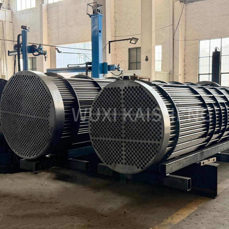
In this context, the company's experienceWuxi Kaisheng Electric Power and Petrochemical Equipment Co., Ltd.serves as a benchmark for quality and technological maturity. Specializing in the design and production of complex heat transfer equipment for the energy and petrochemical industries, the company successfully integrates advanced U-tube manufacturing techniques into its production lines. The company's product portfolio includes not only standard solutions, but also high-tech products: titanium shell-and-tube heat exchangers, ASME high-pressure vessels, as well as tube bundles made from exotic alloys such as C46400 marine brass, C70600 copper-nickel alloys and N06625 nickel alloy. This wide range of materials, from carbon steel to titanium, allows for solutions in the most aggressive environments, including seawater desalination and oil refining processes.
The process begins with incoming inspection of raw materials. The base pipes are checked for compliance with the chemical composition and mechanical properties. We use spectral analysis for each metal melt to ensure that material with deviations in carbon content or alloying elements does not enter production. The finning strip is also tested for thickness and uniformity of structure. Any deviations over 5% from the nominal value are grounds for rejection of the batch.
The key stage is the process of shaping the ribs. When using the high frequency welding method, it is critical to maintain a stable temperature in the contact area. Overheating leads to burnout of alloying elements and the formation of brittle structures in the weld, and underheating leads to lack of penetration. Our production is equipped with automated systems for monitoring welding parameters in real time, which record any deviations and stop the line in the event of an emergency.
After the fins are formed, each pipe undergoes visual inspection and measuring geometry control. The pitch of the fins, their height, perpendicularity to the pipe axis and the quality of the weld fillet are checked. Particular attention is paid to the U-bend area: cracks, corrugations or significant thinning of the wall are not allowed here. For critical orders, we carry out ultrasonic testing (UT) of the bending zone and welds of the ribs for 100% of the length of the product.
Hydraulic testing is a mandatory final step before shipment. Pipes are subjected to pressure 1.5 times higher than the working pressure for a time sufficient to identify hidden defects. Tests are carried out on special stands with recording of pressure and exposure time in an electronic log. Products that do not pass this stage are sent to be melted down or scrapped, never reaching the client.
Product certification includes obtaining quality certificates indicating all the main characteristics: steel grade, dimensions, mechanical test results and non-destructive testing data. For deliveries to high-risk facilities (oil and gas, nuclear energy), a permit from Rostekhnadzor or similar supervisory authorities of import countries is required. Documentation must accompany each shipment of goods and be kept by the customer for the entire service life of the equipment. Wuxi Kaisheng LLC products, certified to PED and ASME standards, fully comply with these stringent requirements, providing customers around the world with stable operation of equipment under high pressure and temperature conditions.
We understand that client trust is built on transparency of processes. Поэтому по запросу заказчика возможна организация инспекции производства сторонними аудиторскими компаниями или представителями технического заказчика. Открытость к проверкам подтверждает нашу уверенность в качестве выпускаемой продукции и соблюдении всех заявленных стандартов. Качество — это не просто слово в маркетинге, а результат ежедневной дисциплины и строгого следования технологическим картам.
Логистика, монтаж и типичные ошибки при установке
Даже идеально изготовленная U-образная оребренная труба может не показать своих преимуществ при неправильной транспортировке или монтаже. Статистика сервисных обращений показывает, что до 30% проблем с теплообменниками возникают именно на этапе монтажа из-за нарушения рекомендаций производителя. Понимание специфики работы с данным типом оборудования позволит избежать дорогостоящих переделок и простоев.
Транспортировка оребренных труб требует особой осторожности. Ребра, несмотря на свою прочность, чувствительны к ударным нагрузкам и сдавливанию. Упаковка должна обеспечивать фиксацию труб в пучке, исключающую их взаимное трение и деформацию при вибрации в пути. Мы используем деревянные каркасы и мягкие прокладки между рядами труб. Загрузка в контейнер должна производиться механизмами с мягкими стропами, не допускается использование стальных цепей без защитных накладок, так как они могут повредить кромки ребер.
При монтаже в трубную решетку теплообменника критически важно соблюдать соосность отверстий. Перекос при забивке трубы может привести к смятию ребер в месте входа в решетку, что нарушит герметичность соединения и создаст зону повышенного сопротивления потоку. Рекомендуется использовать специальные направляющие втулки и смазку, совместимую с материалом трубы, для облегчения посадки. Усилие запрессовки должно контролироваться динамометрическим инструментом.
Одной из самых распространенных ошибок является неправильная сварка труб с трубной доской. Термическое влияние сварки может отпустить металл ребер в непосредственной близости от шва, снизив их прочность. Необходимо применять режимы сварки с минимальным тепловложением и использовать теплоотводящие медные подкладки. Также запрещено варить непосредственно по ребру: сварочный шов должен располагаться только на гладкой части трубы или с отступом, указанным в технологической карте.
Еще один важный аспект — обеспечение компенсаторов теплового расширения в конструкции аппарата. U-образная форма сама по себе является элементом компенсации, но при большой длине прямых участков или жестком креплении корпусов могут возникнуть дополнительные напряжения. Проектная документация должна предусматривать свободное перемещение трубного пучка относительно корпуса или установку линзовых компенсаторов. Игнорирование этого требования часто приводит к разрушению трубных досок после нескольких циклов нагрева и охлаждения.
Первый пуск оборудования должен проводиться в щадящем режиме. Резкий нагрев холодной системы горячим теплоносителем вызывает термический шок, который опасен для сварных соединений. Рекомендуется повышать температуру постепенно, со скоростью не более 30–50°C в час, контролируя состояние уплотнений и фланцевых соединений. Только после выхода на рабочий режим и стабилизации параметров можно говорить о штатной эксплуатации.
Регулярное техническое обслуживание включает в себя визуальный осмотр состояния ребер и очистку межреберного пространства. Методы очистки зависят от типа загрязнений: для сухой пыли подходит обдувка сжатым воздухом, для липких отложений — химическая промывка или гидродинамическая очистка водой под высоким давлением. Важно не повредить ребра струей воды: давление не должно превышать значений, рекомендованных производителем, обычно это 10–15 МПа при правильном угле подачи.
Коммерческие условия поставки и сотрудничество с производителем
Закупка промышленного оборудования — это инвестиционное решение, требующее четкого понимания коммерческих условий и гарантий со стороны поставщика. Работа с прямым производителем U-образных оребренных труб с продольными ребрами дает ряд преимуществ по сравнению с покупкой через торговых посредников, включая возможность кастомизации продукции под специфические задачи проекта и прямой контроль сроков изготовления.
Минимальный объем заказа (MOQ) зависит от сложности конфигурации трубы и используемых материалов. Для стандартных изделий из углеродистой стали минимальная партия составляет 500 погонных метров или 50 штук готовых U-образных элементов. Для заказов из нержавеющих сталей или спецсплавов MOQ может быть увеличен до 1000 метров из-за особенностей настройки производственной линии и стоимости сырья. Мы готовы рассмотреть индивидуальные условия для крупных инфраструктурных проектов с объемом потребления свыше 10 тонн в месяц.
Сроки изготовления типовых позиций составляют 15–20 рабочих дней с момента подписания спецификации и получения авансового платежа. Производство нестандартных изделий с уникальной геометрией или специальными требованиями к контролю качества занимает от 30 до 45 дней. Мы всегда закладываем временной буфер на логистику и таможенное оформление, чтобы гарантировать поставку точно в срок, указанный в контракте. Задержка поставки по нашей вине компенсируется штрафными санкциями согласно условиям договора.
Ценообразование формируется на основе стоимости металла на бирже LME, трудозатрат на обработку и накладных расходов. Мы практикуем прозрачную систему ценообразования, предоставляя клиентам детализированный расчет стоимости единицы продукции. При заключении долгосрочных контрактов (на срок более 6 месяцев) возможна фиксация цены или использование формульного ценообразования, привязанного к индексам цен на сталь, что защищает обе стороны от резких колебаний рынка.
Гарантийные обязательства распространяются на все виды дефектов manufacturing (производственного характера) в течение 12 месяцев с даты ввода в эксплуатацию, но не более 18 месяцев с даты отгрузки. Гарантия не покрывает повреждения, вызванные нарушением правил монтажа, эксплуатации сверх проектных параметров или действием форс-мажорных обстоятельств. В случае выявления брака мы обязуемся заменить дефектную продукцию за свой счет в кратчайшие сроки, взяв на себя расходы по обратной логистике.
Для иностранных покупателей мы обеспечиваем полное экспортное сопровождение: подготовка документов для таможенной декларации (Инвойс, Packing List, Сертификат происхождения), маркировка согласно требованиям страны назначения и организация доставки до порта отправления или границы. Наличие собственного отдела ВЭД позволяет минимизировать бюрократические задержки и решать вопросы документального оформления оперативно. Мы работаем по предоплате или аккредитиву, условия обсуждаются индивидуально в зависимости от кредитной истории партнера.
Сотрудничество с нами — это доступ к технологиям, проверенным в реальных промышленных условиях, и поддержка квалифицированных инженеров на всех этапах сделки. Мы не просто продаем трубы, мы предлагаем решение вашей задачи по теплообмену, подкрепленное надежной сервисной поддержкой и гарантией качества. Contact us today to discuss the details of your project and receive a quote.
Frequently asked questions (FAQ)
Какой максимальный рабочий давление выдерживают U-образные оребренные трубы?
Максимальное рабочее давление зависит от диаметра трубы, толщины стенки и марки материала. Для стандартных труб диаметром 25–32 мм из стали 20 предел составляет 2.5–4.0 МПа. Для усиленных исполнений из легированных сталей давление может достигать 10.0 МПа и выше. Точное значение определяется расчетом на прочность согласно ГОСТ или ASME для конкретного проекта.
Возможна ли замена гладких труб на оребренные в существующем теплообменнике?
Да, такая модернизация возможна, но требует перерасчета гидравлического сопротивления и тепловой нагрузки. Часто приходится менять количество труб в пучке или схему их расположения, так как оребренные трубы занимают больше места в поперечном сечении. Необходимо заказать инженерный аудит текущего аппарата перед началом работ.
Какой срок службы оребренных труб в агрессивных средах?
При правильном подборе материала (например, сталь 09Г2С или нержавейка) и соблюдении температурного режима срок службы составляет от 5 до 10 лет. В средах с высокой концентрацией серы или хлора ресурс может снижаться до 3 лет без дополнительной защиты. Регулярный мониторинг толщины стенки и состояния ребер позволяет прогнозировать остаточный ресурс.
Предоставляете ли вы образцы продукции для тестирования?
Мы предоставляем образцы длиной до 1 метра для проведения лабораторных испытаний и проверки качества сварки. Образцы отгружаются в течение 3 дней после запроса. Стоимость образца и доставки оплачивается заказчиком, но эта сумма вычитается из счета при размещении первого полноценного заказа.
Есть ли у вас сертификаты EAC и ISO для экспорта в страны СНГ?
Да, вся наша продукция сертифицирована по системе ГОСТ Р и имеет декларацию соответствия ТР ТС (EAC). Завод сертифицирован по ISO 9001:2015. При необходимости мы можем оформить дополнительные сертификаты страны назначения или пройти инспекцию международного бюро верификации.