
Heat exchanger tube sheet: flaw detection of seams
2026-10-03
- Heat exchanger tube sheet: seam flaw detection as a critical quality control step
- Methods for flaw detection of tube sheet seams: comparative analysis
- Surface preparation and inspection technology
- Regulatory framework and rejection criteria
- Практические рекомендации для заказчиков и производителей
- Frequently Asked Questions
- Conclusion and next steps
Heat exchanger tube sheet: seam flaw detection as a critical quality control step
Flaw detection of the seams connecting the pipes to the heat exchanger tube sheet is the only reliable way to prevent leaks of high-pressure process media. In our practice, we have observed cases where visual inspection missed microcracks less than 0.1 mm in size, which after three months of operation led to mixing of circuits and shutdown of the entire oil refining unit. The article is devoted to detailed methods of non-destructive testing (NDT), the specifics of preparing rolling and welding zones, as well as interpretation of the results in accordance with GOST and international standards. If you are involved in the acceptance of equipment or the production of shell-and-tube heat exchangers, ignoring these procedures carries direct financial risks.
Why is the area between the pipe and the grate the most vulnerable spot?
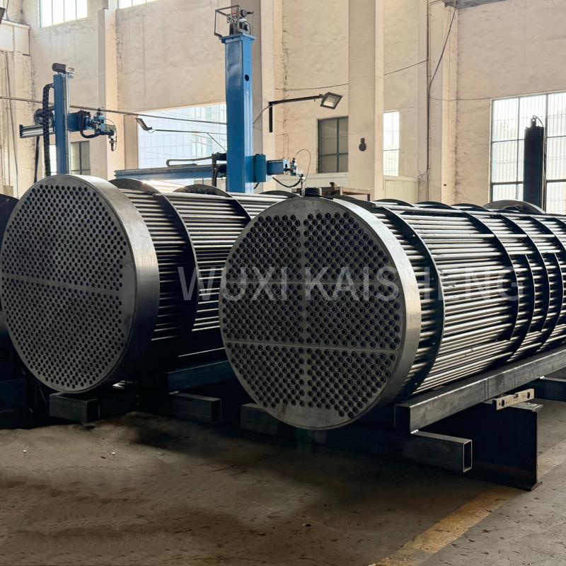
The design of the tube sheet involves hundreds of holes into which heat exchange pipes are installed. It is at the point where the metal of the pipe passes into the metal of the grating that maximum thermal and mechanical stresses arise. During cyclic heating and cooling, the coefficients of linear expansion of the pipe and grid materials may differ, which creates variable loads on the weld or rolling zone. Failure statistics show that more than 65% of all leaks in shell-and-tube devices occur in this area.
One of our clients was faced with a situation where a steam condenser failed six months after installation. The reason lay not in the corrosion of the material, but in the lack of penetration of the root of the seam when welding the pipe to the grating. The defect was hidden under a layer of deposited metal and was not detected during incoming inspection. The consequence was that steam entered the cooling water circuit, which led to water hammer in the water treatment system and damage amounting to four times the cost of the heat exchanger itself. This case proves: saving on high-quality flaw detection of tube sheet seams always costs more.
The complexity of control is aggravated by the geometry of the node. The clearance between the pipe and the wall of the grid opening is often minimal, and scanning access is limited to adjacent pipes. Traditional methods that work on large planes are often inapplicable here without special adaptation of sensors (transducers) and equipment. Therefore, the approach toflaw detection of seamsmust be strictly regulated by a technological map, taking into account the diameter of the pipes, the thickness of the grid wall and the type of connection.
It is important to understand the difference between joints made by rolling only, welding only, or a combination of both. In the case of clean rolling, control is aimed at identifying leaks and insufficient tension. When welding, the priority shifts to searching for cracks, pores and lack of fusion. The combined method (rolling followed by welding) requires a two-stage test, since the thermal effect of welding can disrupt the tightness of the previously performed rolling. The choice of NDT technique depends on the project requirements and work environment.
These issues become especially relevant when working with complex alloys. For example, a companyWuxi Kaisheng LLC, specializing in the production of high-pressure heat transfer equipment for the oil, gas and energy industries, pays close attention to the quality of connections in devices made of titanium, nickel alloys (such as N06625) and marine brass. Their experience shows that when producing tube bundles from highly corrosion-resistant materials certified to ASME and PED standards, even microscopic defects in the rolling or welding zone can become hot spots for rapid stress corrosion. That is why manufacturers of this level integrate multi-stage control directly into the assembly process cycle, using advanced diagnostic methods even at the stage of tube sheet formation.
Methods for flaw detection of tube sheet seams: comparative analysis
The choice of monitoring method is determined by the required sensitivity, access to the monitoring area and the project budget. At the present stage of industrial development, ultrasonic methods are most in demand, but capillary and radiation testing retain their niches. Below is a detailed breakdown of the main technologies used to inspect pipe-to-grid connections.
Ultrasonic testing (UT): pulse echo and phased array
Ultrasonic testing remains the gold standard for identifying internal defects in weld metal and heat-affected zones. The classic pulse echo method uses a single transducer that emits and receives a signal. For tube sheets, special prisms are used that allow the wave to be introduced at an angle necessary to detect radial and axial cracks. The advantage of the method is its high penetrating ability and the ability to assess the depth of the defect.
However, traditional ultrasonic testing has a limitation in the form of a “dead zone” near the surface, where the signal from the surface wave masks small defects. In our practice, we encountered this when inspecting thin-walled stainless steel pipes: cracks 0.5 mm deep at the root of the weld remained invisible when using standard frequencies of 2.5 MHz. The solution required a transition to high-frequency converters (5-10 MHz) and the use of low-viscosity coupling fluids.
Phased Array Ultrasonic Testing (PAUT) technology has revolutionized the approach to tube array inspection. The use of multi-element transducers allows the beam entry angle to be electronically changed without mechanically moving the sensor. This is critical for tube bundles where physical access is limited. Using PAUT, you can obtain a sector scan (S-scan), which visualizes the weld cross-section in real time. We record a 40% increase in inspection speed and a reduction in the human factor when interpreting data compared to manual ultrasonic testing.
When working with PAUT, the grating material must be taken into account. The coarse grain structure of cast steel gratings can cause strong ultrasound scattering, creating structural noise. In such cases, careful adjustment of filters and the use of low frequencies is required, which reduces resolution. Always carry out test measurements on witness samples (calibration blocks) with artificial defects that simulate real discontinuities before starting the main work.
Penetrant testing (PC) and color flaw detection
Penetrant testing is intended exclusively for identifying surface defects: cracks, pores, lack of fusion extending to the surface. The method is based on the penetration of indicator liquid (penetrant) into defect cavities under the action of capillary forces. For tube sheets, this is often the first inspection step after cleaning the seams. The process includes cleaning, application of penetrant, removal of excess, application of developer and visual inspection.
The main advantage of a PC is the simplicity and low cost of the equipment. No complex electronics or power supplies are required, making the method ideal for field applications or hard-to-reach areas within the heat exchanger housing. However, the method has a significant drawback: it does not provide information about the depth of the defect. A crack 0.1 mm deep and a through fistula will look the same - like a bright line on a white developer background. In addition, the method is not useful for porous materials or dirty surfaces.
An important nuance that is often forgotten: the sensitivity of capillary control directly depends on the ambient temperature and surface cleanliness. At temperatures below +10°C, the holding time of the penetrant must be increased, otherwise the liquid will not have time to penetrate the microcracks. One of our engineers made the mistake of conducting testing in winter in an unheated workshop without adjusting the exposure time. The result was the passage of a network of microcracks that opened during the first hydraulic test. Always adhere to the temperature conditions specified in the regulations for the kit of materials used.
There are two main types of penetrants: visible (colored, usually red) and luminescent. Luminescent materials require ultraviolet (UV-A) illumination and provide higher sensitivity, allowing the detection of defects as small as 1 micron in width. For critical heat exchanger units operating with aggressive media or under high pressure, we recommend using the luminescent method of sensitivity class 2 or 1 according to GOST R 56512.
Radiation monitoring (RM) and gamma flaw detection
Radiation testing allows you to obtain an objective image of the internal structure of the seam on film or a digital detector. This is the only method that provides documented quality in the form of a radiographic image that can be archived and rechecked years later. For tube sheets, RK is used less frequently due to the complexity of the geometry: many pipes create overlaps in the image, making it difficult to decipher.
The efficiency of the RC drops sharply as the number of rows of pipes increases. It is almost impossible to illuminate the central bundle of tubes through the peripheral rows without the use of special collimators and high energy sources. However, for outer rows of pipes or single connections, the method is indispensable. It perfectly detects volumetric defects: slag inclusions, pores, lack of fusion across the cross section. The sensitivity of the method allows recording changes in metal thickness within 1-2%.
Safety when performing RK is a critical factor. Working with sources of ionizing radiation requires the organization of a sanitary protection zone, the presence of dosimetric monitoring and specially trained personnel. In the conditions of existing production, stopping related work during candling may be economically unprofitable. Therefore, RK for tube sheets is more often used at the stage of factory production, when the device has not yet been fully assembled, or for selective monitoring of critical areas.
| Comparison parameter | Ultrasonic testing (UT/PAUT) | Penetrant control (PC) | Radiation control (RK) |
|---|---|---|---|
| Type of defects detected | Internal and surface (cracks, lack of penetration, delamination) | Only superficial (open cracks, pores) | Internal volumetric (pores, slag, lack of penetration) |
| Depth | Accurately determined (mm) | Not defined | Visible on projection, depth is estimated indirectly |
| Required access | Requires contact with the surface, can work in hard-to-reach places | Direct visual access is required | Two-way access (source and film/detector) |
| Speed control | High (especially PAUT) | Medium (depends on drying time) | Low (preparation, exposure, development) |
| Security | Safe for the operator | Safe (chemical reagents require ventilation) | Requires strict radiation protection |
| Implementation cost | High (PAUT equipment) | Low | Medium/High (sources, protection) |
Surface preparation and inspection technology
The quality of flaw detection depends 80% on the correct preparation of the controlled area. Even the most modern PAUT scanner will show false signals if the surface of the pipe or grate is covered with scale, rust or grease residue from rolling. The GOST R 56512 and ISO 17640 standards impose strict requirements on surface roughness. For ultrasonic testing, the Ra parameter should not exceed 6.3 µm, and for capillary testing, the surface should be almost mirror-like after etching.
The preparation process begins with mechanical cleaning. The use of abrasive wheels must be done carefully so as not to smear the defect with metal shavings or to overheat the metal, causing tempering colors that can distort the results of penetrant testing. After cleaning, degreasing with solvents that do not leave a film is required. Acetone or specialized NDT cleaners work best. We recommend wiping the control area with a white cloth: if traces of dirt remain on it, repeat the cleaning procedure.
When performing ultrasonic testing, acoustic contact is critical. Using an unsuitable coupling fluid may result in signal attenuation. For vertical surfaces or ceiling joints, gel-like contact media with high adhesion are required. In cold environments, conventional gels freeze, losing their properties, so in winter you should use anti-freeze formulations based on glycol or alcohol. Ignoring this rule leads to the appearance of a “noise track” on the flaw detector screen, masking the real reflectors.
Particular attention is paid to equipment calibration. Before the start of each shift, the operator is required to set up the device using standard samples (SOP). For tube sheets, SOPs are used with defect simulators in the form of flat-bottomed holes or cuts located in the fusion zone of the pipe and the sheet. The gain (sensitivity) is adjusted so that the signal from the reference defect occupies a certain height on the screen (usually 80%). Recording the settings in the control log is mandatory - this is the first thing the customer’s technical supervision checks.
Typical mistakes when flaw detection of seams
The first common mistake is the incorrect choice of the ultrasonic wave input angle. Operators often use standard angles (45°, 60°, 70°) without considering the geometry of the specific joint. If the angle is chosen incorrectly, the beam may be reflected from the pipe wall without entering the risk zone - the root of the seam. We have seen cases where marriages were missed precisely because of this. Solution: calculate the beam path in specialized software or use PAUT sector scanning, which covers the entire range of angles.
The second error concerns the interpretation of signals from structural elements. A height transition between pipe and grate, a weld fillet, or a change in metal grain produces strong echoes that can be mistaken for a crack by an inexperienced operator. Conversely, the orientation of the crack may be such that it does not reflect the wave back to the transducer. To avoid false conclusions, it is necessary to scan the area from different sides and different angles. If the signal does not change when the input angle changes, it is most likely a structural reflector. If the signal “jumps” or disappears, there is a high probability of a plane defect.
The third mistake is violation of time intervals during capillary control. The holding time of the penetrant and developer is indicated in the instructions for a reason. Reducing the exposure time in a hurry leads to the fact that the penetrant does not have time to escape from narrow cracks to the surface, and the defect remains invisible. This is especially critical at low temperatures. The rule is simple: when in doubt, hold on longer. An extra 5 minutes is not worth the risk of missing a fistula.
Regulatory framework and rejection criteria
Evaluation of flaw detection results is carried out strictly in accordance with regulatory documentation. In Russia and the CIS countries, the main document is GOST R 56512-2015 “Non-destructive testing. Welded joints. Quality levels." For equipment operating under pressure, the Rules for the Design and Safe Operation of Pressure Vessels (PB 03-576-03) also apply. At the international level, they focus on ASME Section VIII Div. 1 or EN ISO 5817.
Rejection criteria depend on the category of the vessel and the properties of the working environment. For heat exchangers operating with toxic or explosive substances, the requirements are maximum. Typically, any cracks are unacceptable, regardless of their size and location. Lack of weld root penetration is also completely prohibited. Single pores of a certain diameter are allowed, but their total area in a given area should not exceed a specified percentage of the seam area.
With ultrasonic testing, the assessment is based on the amplitude of the echo signal and its length. Defects are classified according to their conventional sizes. If the equivalent defect area exceeds the acceptable limit for a given quality level (eg ISO 17640 Level B), the connection must be repaired or rejected. It is important to note that the standards are updated periodically. For example, the transition to new editions of GOST may tighten the requirements for the permissible sizes of discontinuities. Всегда используйте актуальные версии документов, действующие на момент сдачи объекта.
Документирование результатов — неотъемлемая часть процесса. Протокол дефектоскопии должен содержать схему расположения труб, карту дефектов с привязкой координат, настройки прибора и заключение о годности. В эпоху цифровизации все больше компаний переходят на электронные паспорта оборудования, где данные НК загружаются напрямую из прибора. Это исключает человеческий фактор при переписывании данных и позволяет отслеживать развитие дефектов в динамике при последующих обследованиях.
Практические рекомендации для заказчиков и производителей
Если вы заказываете изготовление теплообменника, включите в техническое задание требование о предоставлении протоколов НК на 100% соединений труб с решеткой, а не выборочно. Выборочный контроль (например, 10% труб) допустим только для аппаратов низкого давления и неответственного назначения. Для энергетического и нефтехимического оборудования тотальный контроль является необходимостью. Уточните метод контроля: для высоконагруженных узлов настаивайте на применении PAUT или комбинации УЗК и капиллярного метода.
Производителям рекомендуется внедрять автоматизированные системы сканирования для трубных пучков. Ручной контроль тысяч соединений — это тяжелый труд, ведущий к усталости оператора и снижению внимания. Роботизированные сканеры, перемещающиеся по шаблону решетки, обеспечивают стабильность прижима датчика и неизменность скорости сканирования. Инвестиции в такое оборудование окупаются за счет снижения рекламаций и повышения пропускной способности цеха.
Не забывайте о квалификации персонала. Наличие удостоверения НАКС (Национальное агентство контроля сварки) или сертификата по ISO 9712 обязательно. Но бумага не гарантирует мастерство. Проводите практические тесты для операторов на реальных образцах с известными дефектами перед допуском к работе на вашем объекте. Мы знаем случаи, когда аттестованный специалист не мог найти искусственный пропил на тестовом блоке из-за отсутствия практики с конкретным типом оборудования.
Учитывайте материал трубной решетки. При контроле биметаллических решеток (например, сталь с наплавленным слоем нержавейки) возникает дополнительная граница раздела сред, дающая сильные помехи. Требуется специальная методика, учитывающая скорость звука в наплавленном слое. Игнорирование этого фактора приведет к тому, что вы будете контролировать только основной металл, оставляя зону наплавки, где чаще всего возникают коррозионные трещины, без внимания.
Frequently Asked Questions
Какой метод дефектоскопии швов трубной решетки самый точный?
Не существует единственного «самого точного» метода для всех ситуаций. Наиболее полную картину дает комбинация методов. Ультразвуковой контроль с фазированными решетками (PAUT) обеспечивает лучшую глубину проникновения и определение размеров внутренних дефектов. Капиллярный контроль незаменим для поиска мельчайших поверхностных трещин, которые могут быть не видны на УЗИ из-за ориентации. Для максимальной надежности мы рекомендуем использовать связку PAUT + ПК. Это покрывает 99% возможных типов несплошностей.
Можно ли проводить дефектоскопию на уже установленном теплообменнике?
Да, это возможно, но с ограничениями. Доступ к трубной решетке внутри кожуха часто затруднен. Для внутреннего пучка труб полный контроль без разборки аппарата невозможен. Обычно проверяют периферийные ряды труб, доступные для ввода датчика через люки, или используют специальные длинные гибкие сканеры. Если теплообменник демонтирован, контроль проводится полноценно со стороны межтрубного пространства. Планируйте возможность доступа для НК еще на стадии проектирования установки.
Что делать, если обнаружен дефект в сварном шве?
При обнаружении недопустимого дефекта составляется карта ремонта. Шов подлежит вырубки механическим способом (фрезеровка, шлифовка) до здорового металла. Затем выполняется повторная заварка по утвержденной технологии. После ремонта обязательно проводится повторная дефектоскопия того же участка тем же методом, которым был найден дефект, плюс дополнительным методом для страховки. Важно не перегреть соседние трубы при вырубке, чтобы не нарушить их соединения с решеткой.
Как часто нужно проводить повторную дефектоскопию в процессе эксплуатации?
Периодичность определяется регламентом технического диагностирования предприятия и условиями эксплуатации. Для аппаратов, работающих в агрессивных средах или при высоких циклических нагрузках, рекомендуемый интервал — каждые 2-4 года или во время плановых капитальных ремонтов. Внеочередной контроль назначается при подозрении на утечку, после гидроударов или аварийных остановок. Мониторинг состояния трубных решеток входит в систему управления целостностью оборудования (RBI).
Conclusion and next steps
Качественнаядефектоскопия швовтрубной решетки — это не просто формальное соблюдение норм, а реальная инвестиция в безопасность и бесперебойность вашего производства. Игнорирование микротрещин сегодня может обернуться масштабной аварией завтра. Современные методы, такие как PAUT, позволяют видеть невидимое и предотвращать катастрофы до их начала. Мы призываем не экономить на этапе контроля качества и требовать от поставщиков прозрачных протоколов испытаний.
Если вы столкнулись с необходимостью проведения экспертизы теплообменного оборудования, выбора методики контроля или интерпретации сложных результатов дефектоскопии, наша команда готова оказать профессиональную поддержку. Мы обладаем парком современного оборудования и штатом сертифицированных экспертов уровня III по ISO 9712.Contact us todayдля обсуждения деталей вашего проекта и получения консультации.
Для получения дополнительной информации о стандартах неразрушающего контроля рекомендуем ознакомиться с материаламиИсточник: Ассоциация «ОКСНК», где представлены актуальные разъяснения по применению ГОСТ Р 56512-2015.