
Assembly of a heat exchanger tube bundle: main steps
2026-09-30
- Assembly of a heat exchanger tube bundle: main steps and critical control points
- Component Preparation: Why Cleanliness is More Important than Speed
- Sequential assembly of a tube bundle: from the first pipe to the complete package
- Flaring technology: creating a tight connection
- Quality control and elimination of assembly defects
- Packaging, labeling and preparation for shipment
- Frequently Asked Questions
- Conclusion and next steps
Assembly of a heat exchanger tube bundle: main steps and critical control points
The process of assembling a bundle of heat exchanger tubes determines up to 80% of the reliability of the entire device in operation. We have seen cases where a perfectly welded housing has been rendered useless by a 3 millimeter misalignment of the tube bundle, resulting in the inability to install caps and subsequent leaks under pressure. In this article we will analyze not just a theoretical sequence of actions, but a real production cycle, including preparation, installation, rolling and hydraulic testing. Our goal is to give you a clear understanding of how a quality product is formed that meets GOST and ASME standards, so that you can evaluate suppliers not by pretty pictures, but by technological discipline.
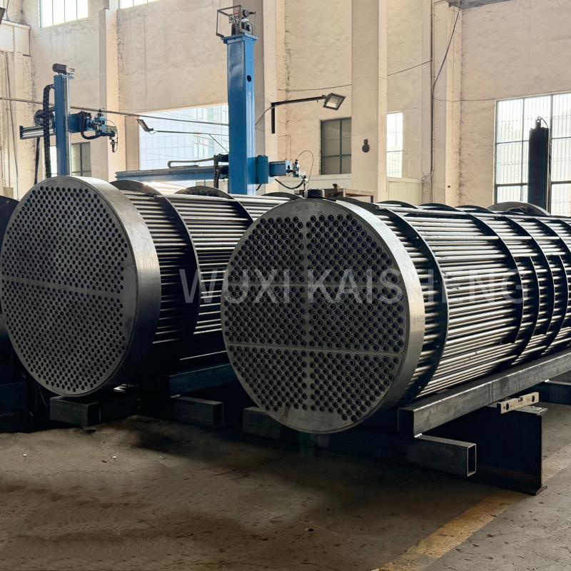
Assembly of the heat exchanger tube bundle: the main stages of this process require strict adherence to geometry and cleanliness of surfaces. Any deviation at the preparation stage leads to an avalanche-like growth of defects in the final stages. Below we describe each step in detail, based on our experience of producing more than 500 units of heat exchange equipment annually for the oil, gas and chemical industries. This is exactly the approach the company takesWuxi Kaisheng Electric Power and Petrochemical Equipment Co., Ltd., specializing in the development and production of complex heat exchange systems. Our portfolio includes titanium shell and tube heat exchangers, ASME pressure vessels, 316 stainless steel corrugated tube bundles, as well as C46400 marine brass, copper-nickel and N06625 nickel alloy solutions. By using materials with high corrosion resistance and complying with international standards (PED, ASME), we ensure stable operation of equipment in the most aggressive environments of oil refining, chemical industry, water desalination and shipbuilding.
Component Preparation: Why Cleanliness is More Important than Speed
The start of work always begins with incoming inspection of materials, and this is the stage where saving time is unacceptable. Pipes, tube sheets and partitions must undergo mandatory cleaning to remove preservative oils, oxide films and mechanical contaminants. We use a three-stage cleaning system: chemical degreasing, mechanical cleaning of pipe ends with abrasive materials and final rinsing with demineralized water. If you skip this step, residual oil will enter the rolling zone, creating a lubricating effect that will not allow you to create a tight pipe-grid connection. One of our clients was faced with a situation where a batch of heat exchangers began to leak after a month of operation precisely because of traces of oil on the ends of AISI 321 stainless steel pipes.
The geometry of the tube sheets is checked with an accuracy of 0.05 mm. Holes for pipes must have a strictly defined gap. According to standardGOST R 53683-2009, the gap between the pipe and the hole in the grill is usually from 0.2 to 0.4 mm depending on the diameter of the pipe. Too large a gap will require excessive deformation of the pipe during rolling, which can lead to thinning and rupture. Too small a gap will make assembly impossible without using force, which will damage the protective layer of metal. We recommend that you always request a protocol for incoming inspection of hole sizes from the manufacturer before starting bundle assembly. At Wuxi Kaisheng, geometry control extends beyond standard steel gratings to complex C46400 brass, C70600 copper-nickel alloys and other specialty materials where tolerances are critical.
Pipes are cut to size taking into account compensation for rolling. The length of the pipe should exceed the thickness of the tube sheet by the amount necessary to form the rolling zone (usually 2-3 mm on each side), but no more, so as not to create zones of stagnation of liquid or unnecessary resistance to flow. Cutting is carried out exclusively mechanically (pipe cutters) or laser, followed by deburring. Gas cutting is strictly prohibited for heat exchanger pipes, as it changes the structure of the metal in the cutting area and creates an uneven edge that cannot be flared properly.
Partitions (deflectors) are also tested for alignment of the holes. The package of partitions is assembled on technological pins, and a gauge simulating a pipe is pulled through them. If the gauge does not pass freely through the entire package, it means that the holes are misaligned, and during assembly the pipes will experience constant stress, leading to fatigue failure. In our practice, we have encountered cases where ignoring this simple test resulted in the beam simply not fitting into the heat exchanger body due to the total accumulated displacement in 10-15 partitions.
Recommendation:Before starting assembly, make sure that you have an incoming inspection certificate for all components. Do not begin installation if the pipes have visible scratches with a depth of more than 5% of the wall thickness or if the ends of the pipes are not perpendicular to the axis.
Sequential assembly of a tube bundle: from the first pipe to the complete package
Assembling the heat exchanger tube bundle: the main installation steps require a strict sequence of installation of the tubes into the grid. There are two main methods: sequential installation of pipes one at a time and pre-assembly of modules. For large devices with more than 500 pipes, we use the layer-by-layer assembly method using conductors. This allows you to maintain the geometry of the bundle and prevents the pipes from sagging under their own weight, which can reach several centimeters over a length of 6 meters.
- Fixing the first tube sheet.The grate is installed in a vertical or horizontal position (depending on the type of slipway) and is rigidly fixed. It is important to ensure that the grating plane is horizontal using precision levels. Any tilt will cause the pipes to enter the holes at an angle, creating initial bending stresses.
- Installation of spacer rods and studs.Temporary guide pins are installed through the holes for future pipes. They serve as a guide for putting on the partitions. The distance between the partitions must strictly correspond to the drawing. Deviation of the baffle pitch by more than ±2 mm changes the hydrodynamics of the flow and can cause vibration of the pipes.
- Installation of partitions.The partitions are put on the studs in a strictly defined order. Note the orientation of the segmental cutouts in the partitions. They should be located according to the coolant movement pattern (usually alternately up and down or in a checkerboard pattern). An error in the orientation of even one partition can create a stagnation zone where local overheating or scale formation will occur.
- Pipe insertion.The pipes are introduced through the openings of the first grid and pass through all the partitions to the second grid. This process requires care. Do not use hammers to hammer in pipes. If the pipe does not move manually or with minimal effort, it is necessary to stop work and find out the reason (burr in the hole, displacement of the partition). Forced insertion damages the surface of the pipe and hole, making high-quality rolling impossible.
- Fixing the second grid.After installing all the pipes, the second tube sheet is slid over the ends of the pipes and secured to the technological supports. At this stage, the beam frame is formed. It is important to check that all pipes come out the same length on the other side. The spread of pipe end lengths should not exceed 1-2 mm.
Particular attention should be paid to the weight of the bundle. For long heat exchangers (more than 4 meters), the own weight of the bundle can cause deflection. We use intermediate supports, which are removed only after the final fixation of the beam in the housing or after welding the second grid to the pipes (if the design provides for preliminary welding). Ignoring gravity is a common mistake in small workshops, leading to the fact that the lower pipes of the bundle are tense, while the upper ones are free, which disrupts the uniformity of heat transfer.
During the assembly process, we often encounter the problem of pipes “biting” in the partitions. This occurs if the holes in the partitions are elliptical instead of round. To avoid this, we require partition suppliers to have laser cutting and stress relief certificates. Cheap partitions, cut by plasma without finishing, have a riveted edge that literally “eats” the pipe during installation.
Recommendation:Keep an assembly log, recording the row number and installation date of each layer of pipe. This will allow you to track at what stage contamination or damage may have occurred if defects are subsequently identified.
Flaring technology: creating a tight connection
Expanding is the most critical stage where the tightness of the “pipe-tube sheet” assembly is formed. This is where two different metals are connected, and the quality of this connection determines the service life of the device. There are several methods: mechanical flaring with a roller reamer, hydraulic flaring and explosive flaring. In mass production, we mainly use the mechanical method with pneumatic or electric drive, as it allows precise dosing of force.
The essence of the process is the plastic deformation of the pipe inside the grid hole. The expander rollers press on the inner wall of the pipe, increasing its diameter until it is pressed tightly against the wall of the grid opening. In this case, the lattice material also receives elastic deformation. After removing the tool, the grid tends to return to its original state, squeezing the pipe with enormous force. This creates contact pressure sufficient to seal and transfer shear forces.
The critical parameter is the degree of flaring. It is calculated using a formula that takes into account the gap, the wall thickness of the pipe and grate, as well as the mechanical properties of the materials. Insufficient flaring will lead to leaks immediately during hydraulic tests. Excessive flaring is more dangerous: it can lead to thinning of the pipe wall below the permissible minimum, the appearance of microcracks on the inner surface of the pipe, or even rupture of the grid material around the hole. We use digital torque sensors on our machines, which automatically stop the process when a preset torque is reached, eliminating human error. We take particular care when working with exotic alloys such as titanium or nickel alloy N06625, which require individual selection of deformation modes due to their high strength and tendency to work hardening.
The length of the flaring zone is also strictly regulated. Usually it is 1.5–2 times the thickness of the tube sheet, but not less than 10-15 mm. If you flare the pipe to the full thickness of the grate without taking into account the outlet, you can deform the end of the pipe, which will make it difficult to install plugs or covers. On the other hand, a contact area that is too short will not provide the required pullout strength.
A common mistake we have seen from subcontractors is lack of lubrication or use of the wrong lubrication when flaring. A special lubricant reduces friction between the rollers and the pipe, ensuring uniform deformation. Without it, the rollers can slip, leaving spiral grooves on the inner surface of the pipe that become hot spots for corrosion. In one case, the use of technical oil instead of a specialized emulsion led to oil getting into the contact zone, and after the metal cooled, the connection lost tension.
For heat exchangers operating under conditions of high vibration or thermal cycling, we use a combined method: flaring followed by welding of the pipe end (strength welding + seal rolling) or vice versa. This provides double protection: mechanical strength due to welding and tightness due to rolling. However, this method requires highly qualified welders and careful control of the quality of the seam.
Recommendation:Require the manufacturer to provide a flaring card indicating the force (torque) for each batch of pipes and gratings. Carry out selective control of the quality of flaring by measuring the internal diameter of the pipe before and after the operation.
Quality control and elimination of assembly defects
Once mechanical assembly and flaring have been completed, the bundle is not considered ready until a series of proof tests have been completed. At this stage, hidden defects that cannot be seen visually are identified. Primary inspection includes a visual inspection of all rolling joints. We use 10x magnification loupes to look for hairline cracks, burrs, and bead unevenness.
The next stage is a leak test using air pressure (bubble method). The bundle is immersed in a bath of water (or the rolling areas are coated with a soap solution), and compressed air at a pressure of 0.2–0.3 MPa is supplied inside the pipes. The appearance of bubbles indicates a leaky connection. This method allows you to identify up to 95% of flaring defects. If a leak is detected, re-flashing is performed. However, it is important to remember: the same pipe can be re-rolled no more than twice. The third attempt is almost guaranteed to lead to hardening of the metal and its destruction. In such cases, the pipe has to be plugged (replaced with a plug), which reduces the heat exchange area of the device.
For critical applications (high pressure, toxic environments), we carry out testing using non-destructive testing (NDT): penetrant testing (color flaw detection) or eddy current testing. The eddy current method is especially effective for identifying cracks inside the rolling zone where there is no visual access. It allows you to evaluate the degree of interference and the presence of gaps between the pipe and the grid without destroying the unit. Wuxi Kaisheng LLC's PED and ASME certified products undergo similar rigorous testing, ensuring reliability even in extreme power and petrochemical environments.
Geometric control of the beam is carried out using templates and laser scanners. The straightness of the pipe axes, the absence of deflections and the compliance of the overall dimensions of the bundle with the internal diameter of the heat exchanger body are checked. The gap between the bundle and the body should be minimal (usually 3-5 mm radially) to exclude bypass flow of coolant past the bundle, which sharply reduces the efficiency of the device. If the bundle dangles in the housing, the efficiency of the heat exchanger may drop by 15-20%.
We also monitor the cleanliness of the internal cavities of pipes. After all mechanical operations, chips, abrasive or scale may remain inside the pipes. High pressure washing and endoscopic inspection are mandatory before packaging. The entry of foreign objects into the pipes of an operating heat exchanger can lead to clogging of the downstream nozzles or local overheating.
Recommendation:Do not accept the bundle without a pneumatic test certificate. Ask for a photo or video of the leak testing process, especially if you cannot be at the plant in person.
Packaging, labeling and preparation for shipment
The finished tube bundle is a precision instrument that requires careful handling during transportation. Even small impacts can disrupt the geometry of thin-walled pipes or damage rolling joints. Packaging begins with the application of a preservative composition to all metal surfaces that do not have a factory coating. We use corrosion inhibitors that create a thin film that protects the metal from moisture for 12 months.
The ends of the pipes must be closed with plastic or wooden plugs. This prevents dirt, moisture and insects from getting inside the pipes. The plugs should fit tightly and not fall out when shaking. Transport rings or frames are installed on the tube sheets, which distribute the load from the slings when lifted by a crane. Lifting the bundle by the pipes themselves or by the edges of the gratings without special traverses is prohibited - this will lead to deformation.
The marking is applied with indelible paint to the end of the grille and to the transport container. It must contain the order number, bundle number, date of manufacture, direction of flow (if specified by design) and mark of conformity to standards (eg EAC, CE or ASME). Отсутствие четкой маркировки часто приводит к путанице на стройплощадке, когда монтажники пытаются установить пучок в неправильном положении или в неверный корпус.
Для морских перевозок пучки крепятся на деревянных салазках и фиксируются стальными лентами. Между пучком и салазками прокладываются демпфирующие материалы (резина или плотный войлок) для гашения вибраций. Конструкция упаковки должна выдерживать штабелирование, если это предусмотрено условиями логистики. Мы проводим тесты на падение и вибрацию для наших стандартных упаковочных решений, чтобы гарантировать сохранность груза.
Вместе с пучком поставляется паспорт изделия, содержащий результаты всех испытаний, сертификаты на материалы (трубы, решетки, прокладки) и исполнительную схему. Наличие полного комплекта документов является обязательным условием для приемки оборудования заказчиком и ввода его в эксплуатацию надзорными органами.
Recommendation:При получении груза немедленно проверьте целостность заглушек и отсутствие следов ударов на транспортной раме. Любые повреждения упаковки должны быть зафиксированы в акте до распаковки.
Frequently Asked Questions
Какой метод развальцовки лучше: механический или гидравлический?
Ответ зависит от задачи. Механическая развальцовка быстрее и дешевле для массового производства стандартных теплообменников. Гидравлическая развальцовка обеспечивает более равномерное распределение давления по всей длине зоны контакта и лучше подходит для толстостенных труб или материалов с низкой пластичностью (например, титан). В нашей практике для стандартных углеродистых сталей мы выбираем механику, а для высоколегированных сплавов — гидравлику.
Можно ли заменить трубу в уже собранном пучке?
Теоретически да, но это сложный и дорогой процесс. Требуется высверлить старую развальцовку, аккуратно извлечь трубу, не повредив отверстия в решетках и перегородках, затем вставить новую трубу и развальцевать её. Риск повреждения соседних труб и решеток очень высок. Часто проще заглушить дефектную трубу, если их количество не превышает 5-10% от общего числа, чем пытаться заменить её. Полная замена пучка иногда экономически целесообразнее ремонта.
Каков срок службы правильно собранного трубного пучка?
При соблюдении всех технологий сборки, использовании качественных материалов и работе в расчетных режимах (температура, давление, химический состав среды) срок службы пучка составляет 15-20 лет и более. Основной лимитирующий фактор — коррозия и эрозия, а не усталость металла от сборки. Регулярная чистка и контроль толщины стенок труб позволяют продлить ресурс до 25 лет.
Почему важно соблюдать чистоту при сборке?
Загрязнения (масло, пыль, металлическая стружка) действуют как абразив или смазка, мешая созданию плотного контакта между металлами. Масло в зоне вальцовки может выгореть при первом нагреве, оставив микроканалы для утечек. Стружка внутри труб вызовет локальный перегрев и пробой. Чистота — это не просто эстетика, это фундаментальное требование технологии.
Conclusion and next steps
Сборка пучка труб теплообменника: основные этапы этого процесса демонстрируют, что надежность оборудования закладывается не на этапе проектирования, а в цеху, руками сборщиков и контролеров качества. Каждый миллиметр зазора, каждый ньютон усилия развальцовки и каждая частица пыли имеют значение. Игнорирование этих деталей ведет к авариям, простоям и финансовым потерям, которые многократно превышают экономию на качественной сборке.
Мы убеждены, что прозрачность производственного процесса — ключ к доверию между производителем и заказчиком. Понимая, как собирается ваш теплообменник, вы получаете рычаг влияния на качество конечного продукта. Не бойтесь задавать вопросы поставщикам о технологиях вальцовки, методах контроля и квалификации персонала. Хороший производитель всегда готов показать свой цех и документацию.
Если вы планируете закупку теплообменного оборудования или модернизацию существующих линий, важно выбрать партнера с подтвержденной экспертизой. CompanyWuxi Kaisheng Electric Power and Petrochemical Equipment Co., Ltd.готова предложить вам индивидуальные решения высшего качества. Мы производим широкий спектр продукции: от воздушных охладителей и котлов-утилизаторов до сложных трубных пучков из титана, нержавеющей стали 321 и медно-никелевых сплавов. Наши изделия отличаются высокой теплоэффективностью и устойчивостью к экстремальным давлениям и температурам, что делает их идеальным выбором для глобальных проектов в энергетике и нефтехимии.Contact us todayдля консультации по вашему проекту или запроса детального коммерческого предложения. Мы также рекомендуем ознакомиться с нашим материалом отипах кожухотрубных теплообменниковдля полного понимания ассортимента доступных решений.