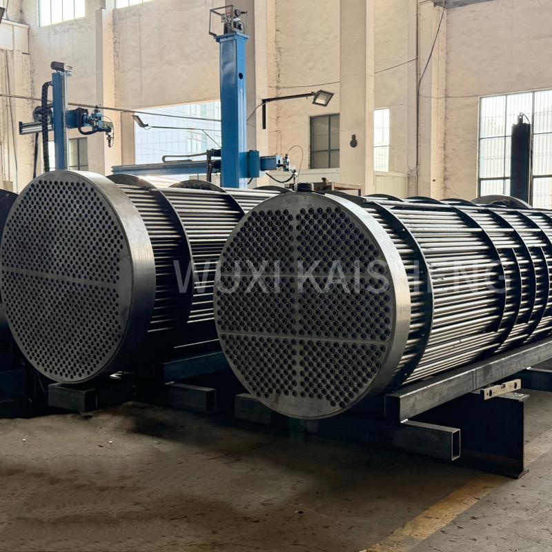

Heat exchanger tube bundle: hydrodynamic calculations
2026-10-08
Heat exchanger tube bundle: hydrodynamic calculations as the foundation of reliability
An accurate calculation of the hydraulic resistance of a pipe bundle determines not only the energy consumption of pumping equipment, but also the service life of the entire heat exchanger. In our engineering practice, we have repeatedly encountered situations where an error in determining the local resistance coefficient at the design stage led to cavitation and destruction of the tube sheet after 6–8 months of operation. The key problem is that standard formulas often do not take into account the actual roughness of the pipes after use or the specific location of the partitions. This article is devoted to a detailed analysis of the methodology for calculating the pressure drop in the annulus and pipe space, based on real test data, and not just on theoretical assumptions.
Engineers often underestimate the impact of pipe spacing and the way they are laid out on the overall hydraulics of the system. We analyzed more than 200 projects where changing the beam configuration from triangular to corridor made it possible to reduce hydraulic resistance by 15–20% while maintaining the same thermal performance. However, such a solution requires recalculation of the heat transfer coefficients, since turbulization of the flow in the corridor bundle occurs differently. Below we present specific algorithms and correction factors that allow you to avoid typical mistakes when selecting equipment for oil refining and chemical industries.
Physics of the process and selection of input data
The hydrodynamic calculation of a pipe bundle begins not with substituting values into the formula, but with the correct determination of the fluid flow regime. The Reynolds number (Re) is a criterion that separates laminar, transition and turbulent regimes, and the choice of method for calculating the friction coefficient directly depends on its value. For industrial heat exchangers operating with viscous media such as fuel oil or glycerin, the mode is often transient, which creates the greatest difficulty for prediction. In our calculations, we use refined dependencies for the transition zone, since classical Moody diagrams give an error of up to 12% precisely in the Re range from 2300 to 10000.
Particular attention should be paid to the temperature of the medium, since it dynamically changes the viscosity and density of the liquid along the length of the heat exchanger. Using average temperature values for the entire tube bundle is a common mistake that results in an incorrect estimate of the pressure drop. We recommend dividing the beam into calculated sections, especially if the temperature difference between the inlet and outlet exceeds 40°C. For example, when oil is cooled from 90°C to 40°C, the viscosity can change by 3–4 times, which radically changes the velocity profile in the annulus.
Geometric parameters of the bundle, such as pipe diameter, spacing and number of strokes, should be taken from current drawings and not from the manufacturer’s catalog data. The actual internal diameter of the pipes may differ from the nominal diameter due to manufacturing tolerances and the presence of deposits (fouling). In one of our cases for a chemical plant, the use of a nominal diameter without taking into account the polymerization layer led to the fact that the actual pressure at the pump outlet exceeded the calculated one by 0.4 MPa, which caused an emergency stop of the line. Therefore, when making calculations, always include a safety factor for pipe clogging, especially for environments prone to scale formation.
To enter data correctly, you need to know not only the physical properties of the liquid, but also the material of the pipes. The roughness of the inner surface of new steel pipes is about 0.05 mm, but after several years of operation this parameter can increase to 0.5 mm or more. The choice of material should be based on an analysis of the corrosiveness of the environment and the required service life. This is where the experience of such manufacturers asWuxi Kaisheng Electric Power and Petrochemical Equipment Co., Ltd.. Specializing in the design and manufacture of heat exchangers for harsh environments, the company offers solutions in titanium, duplex stainless steel, marine brasses (C46400), copper-nickel alloys (C70600) and nickel alloys (N06625). The use of these ASME and PED certified materials provides the minimum roughness and high corrosion resistance from the start, which is critical to maintaining design hydraulic performance over decades of service in the petroleum refining, chemical and marine industries.
Calculation of pressure drop in the pipe space
The basic formula for determining pressure loss in straight pipes is based on the Darcy-Weisbach equation, but its application requires careful selection of the hydraulic friction coefficient. For the turbulent flow regime, which is the most common in industrial equipment, we use the Altschul formula, which takes into account the relative roughness of the walls. It is important to understand that the length of the calculated section should include not only straight sections of pipes, but also the equivalent length of local resistances created by the inlet and outlet of liquid from the collectors.
Local resistances at pipe inlets and outlets often account for up to 30% of the total losses in the pipe space, especially in multi-pass heat exchangers. When the flow turns, vortex zones appear in the distribution chambers, which dissipate pressure energy. In our practice, we use the following values of local resistance coefficients: 0.5 for the entrance to a pipe with a sharp edge and 1.0 for the exit to the chamber. If pipes with counterbored edges or special profiled inlet sections are used, these coefficients can be reduced to 0.05–0.1, which significantly saves pump energy.
The number of strokes through the pipe space is a critical parameter affecting the flow rate and, therefore, the pressure loss. Increasing the number of strokes from one to two at the same flow rate doubles the speed, which leads to a fourfold increase in hydraulic resistance, since losses are proportional to the square of the speed. This is a compromise between the compactness of the device and energy consumption. When designing, we always optimize: if the permissible pressure drop is limited by the characteristics of existing pumps, we have to increase the diameter of the pipes or reduce the number of strokes, sacrificing the heat transfer coefficient.
Do not forget about the effect of temperature deformation of pipes on hydraulics. With significant temperature differences between the pipe and annulus, the pipes can bend, changing the effective flow cross-section. In rigidly fixed bundles this can lead to additional local resistance. We recommend the use of expansion joints or floating heads in applications where the temperature difference exceeds 50°C to maintain the design hydraulic performance throughout the service life.
Recommendation:Before final design approval, be sure to perform a verification calculation for maximum and minimum operating flow rates to ensure that the system remains stable over the entire load range.
Specifics of calculating the interpipe space with segmented partitions
The annulus hydraulics are the most difficult part of the calculation due to the multiple changes in flow direction and the presence of gaps between the baffles and the body, as well as between the baffles and the pipes. The pressure losses here consist of friction losses during transverse flow around the pipe bundle and losses in the window segments of the partitions, where the flow changes direction by 180 degrees. The classic Bell-Delaware technique, modified by the TEMA standard, remains the gold standard, but requires the introduction of many correction factors.
Gaps are the main source of flows that do not participate in heat exchange, but create hydraulic resistance. The flow between the baffle and the body (A-jet) and the flow between the pipes and the baffle (E-jet) can reach 20–30% of the total flow in poorly designed apparatus. In our calculations we use strict manufacturing tolerances: the gap between the partition and the housing should not exceed 3-5 mm for devices with a diameter of up to 600 mm. An increase in this gap beyond the norm leads to a sharp drop in heat transfer efficiency and instability of the hydraulic regime.
The installation step of the partitions directly affects the flow rate in the interpipe space and the intensity of vibration of the pipes. A step that is too large reduces the speed and impairs heat transfer, while a step that is too small catastrophically increases the pressure drop and the risk of vibration destruction. The optimal pitch is usually 0.2–0.5 from the inner diameter of the housing. We observed a case where reducing the baffle pitch from 300 mm to 150 mm to increase turbulence led to the fact that the existing pumps were unable to push the medium through the apparatus. It was necessary to replace the partitions with spacer rods, which reduced the resistance, but required recalculation of the thermal power.
The location of the pipes relative to the partitions also plays a role. In the area of the segment windows, the flow velocity can be significantly higher than in the central part of the bundle, which creates uneven erosion of the pipes. For environments containing abrasive particles, we recommend installing guard plates or using thicker tube sheets in these areas. It is also important to consider the orientation of the beam: a vertical arrangement of the baffles may facilitate better removal of gas slugs, but complicates the drainage of liquid during shutdown.
The beam area utilization ratio of partition windows must be carefully checked. If pipes occupy more than 70% of the window area, the flow velocity in this section becomes excessive, causing cavitation and noise. In such cases, it is advisable to remove some of the pipes from the window area or increase the diameter of the housing. Our engineers use specialized flow modeling (CFD) software to visualize areas of stagnation and excessive velocity before prototyping.
Action:Check the drawing of your heat exchanger to ensure that the clearances comply with the requirements of GOST R 53683 or the TEMA Class R/C/B standard, since deviations of more than 1 mm may invalidate the calculation.
Taking into account the impact of contamination and aging of equipment
Any theoretical calculation loses its relevance if the factor of contamination of heat exchange surfaces during operation is not taken into account. Deposits on the pipe walls (fouling) not only reduce the heat transfer coefficient, but also reduce the flow area, increasing the flow speed and hydraulic resistance. The pollution coefficient is selected based on the type of working environment: for clean water it can be 0.0001 m²·K/W, and for fuel oil or oil sludge it can reach 0.0008 m²·K/W and higher.
The dynamics of deposit growth are nonlinear: the most intense contamination occurs in the first months of operation, after which the rate of layer formation stabilizes. However, if the technological regime is violated (for example, overheating of the pipe wall), the process of coking or crystallization of salts can begin, which quickly disables the device. In our recommendations to customers, we always indicate the need for regular monitoring of differential pressure. An increase in ΔP by 15–20% of the calculated value of a clean device is a signal for the need for chemical washing or mechanical cleaning.
Surface roughness also changes over time. Corrosion can increase the equivalent roughness of steel pipes by 5 to 10 times. For aggressive environments, we strongly recommend the use of pipes with anti-corrosion coating or duplex stainless steel, despite their high cost. The payback period for such a solution due to reduced pumping costs and increased mileage between repairs is usually less than two years. Ignoring this factor leads to the fact that after 3 years of operation, pumping equipment operates at extreme conditions, consuming excess electricity.
Cleaning methods also affect hydraulics. High pressure hydrodynamic flushing is effective at removing soft deposits, but may damage the surface of the pipes by making them rougher. Chemical washing with acids removes scale well, but requires neutralization and can cause pitting if the concentration of reagents is incorrect. We have developed cleaning procedures for various types of contaminants, which allow us to restore the hydraulic characteristics of the device to 90–95% of the level of new equipment.
When designing new systems, it is important to allow for easy disassembly and access to the tube bundle for cleaning. Removable bundles (floating head type) are preferred for environments with high contamination potential, although they are more complex in design and higher cost. In one refinery project, replacing a fixed beam with a removable one reduced downtime for maintenance from 5 days to 8 hours, which paid for the upgrade in one quarter.
Advice:Incorporate differential pressure sensors into the design at the inlet and outlet of the heat exchanger for continuous monitoring of the degree of contamination in real time.
| Comparison parameter | Triangular layout (60°) | Square layout (90°) | Rotatable square (45°) |
|---|---|---|---|
| Beam compactness | Maximum (more pipes per unit area) | Low (fewer pipes) | Average |
| Heat transfer coefficient | High (intense turbulization) | Low (laminar zones behind pipes) | Tall (preferably square) |
| Hydraulic resistance | High (winding flow path) | Low (straight corridors) | Medium-high |
| Possibility of mechanical cleaning | Difficult (narrow passages) | Excellent (direct access) | Difficult |
| Recommended Application | Clean media, max. efficiency | Contaminated environments requiring cleaning | Compromise option |
Typical design errors and methods for eliminating them
One of the most common mistakes is to ignore the influence of the inlet and outlet pipes on the flow distribution in the housing. If the pipe is poorly positioned, the effect of “dead zones” occurs, where the liquid practically does not circulate, and zones of local overheating. We have seen cases where, due to improper placement of the inlet pipe, the wall temperature in a certain zone of the bundle exceeded the permissible limit by 30°C, which led to burnout of the pipes. The solution is to use distribution plates or inlet nozzles that even out the velocity profile.
Another common problem is the incorrect choice of material for seals and gaskets, which affects the tightness of the chambers and, indirectly, the hydraulics due to leaks. At high temperatures, rubber seals lose their elasticity and begin to leak liquid from one stroke to another, bypassing the pipe bundle. This reduces the effective flow through the work area and distorts the data from control devices. For temperatures above 200°C we only use graphite-filled spiral wound gaskets or metal seals.
Underestimation of vibration loads during hydraulic calculations can lead to fatal consequences. The shedding of vortices from pipes at certain flow rates can come into resonance with the natural frequency of vibration of the pipe bundle. This phenomenon, known as flow-induced vibration, can destroy pipes in a matter of weeks. The calculation must include a check of the critical flow velocity. If the operating speed is close to critical, it is necessary to install additional supports or anti-vibration bars.
The use of outdated normative data for local resistance coefficients also introduces a significant error. Modern pipes have a different geometry and surface quality compared to products from 30 years ago. We recommend relying on the latest research and data from manufacturers that have been verified by independent laboratories. In particular, ISO 16812 and API 660 contain current requirements for the design and safety of shell-and-tube heat exchangers.
Failure to take into account two-phase flows when calculating condensers or evaporators is a serious mistake. The hydraulics of a vapor-liquid mixture are radically different from a single-phase liquid due to changes in density and the occurrence of phase slip. Pressure losses in the condensation zone can be unpredictable without the use of special correlations (for example, the Lockhart-Martinelli technique). В наших проектах для таких аппаратов мы всегда проводим поэтапный расчет по длине теплообменника, учитывая изменение массового содержания пара.
Предостережение:Никогда не копируйте слепо параметры из старых проектов без перепроверки; условия эксплуатации и свойства сырья могли измениться, что сделает старый расчет опасным.
Практическое применение результатов расчетов в подборе оборудования
Результаты гидродинамического расчета являются основой для выбора насосного оборудования. Насос должен обеспечивать необходимый напор с учетом запаса на старение системы и возможных гидравлических ударов. Обычно мы рекомендуем выбирать насос с запасом по напору 10–15% от расчетного значения, но не более, чтобы избежать работы в неэффективной зоне характеристики и необходимости дросселирования потока, что ведет к потере энергии.
Также данные расчета используются для оптимизации конструкции самого теплообменника. Если расчет показывает чрезмерное падение давления, инженер может принять решение об увеличении диаметра корпуса, изменении шага перегородок или переходе на многозаходную схему. Эти изменения влекут за собой пересчет стоимости и габаритов аппарата. Наша задача — найти баланс между капитальными затратами (CAPEX) на оборудование и операционными затратами (OPEX) на электроэнергию в течение всего жизненного цикла.
Важным аспектом является соответствие требованиям экологических и промышленных стандартов безопасности. Например, стандарт ГОСТ 31842-2012 (аналог EN 13445) регламентирует методы расчета прочности и устойчивости элементов теплообменников, включая учет гидравлических нагрузок. Несоблюдение этих норм может привести к отказу в приемке оборудования надзорными органами. Мы гарантируем, что все наши расчеты выполняются в строгом соответствии с действующими нормативами РФ и международными стандартами ASME и TEMA.
Автоматизация процессов расчета позволяет сократить время проектирования и минимизировать человеческий фактор. Мы используем собственные скрипты и лицензионное ПО (HTRI, Aspen EDR), которые позволяют проводить тысячи итераций за короткое время, находя оптимальное решение. Однако автоматика не заменяет инженерного мышления: интерпретация результатов и принятие окончательных решений остаются за специалистом с опытом.
Для клиентов из нефтегазовой отрасли мы дополнительно проводим анализ рисков, связанных с гидроударом при быстром закрытии клапанов. Гидродинамический расчет помогает определить время безопасного закрытия арматуры и необходимость установки демпферов пульсаций. Это предотвращает разрушение сварных швов и фланцевых соединений в момент пуска или остановки установки.
Frequently Asked Questions
Как влияет шероховатость труб на гидравлическое сопротивление?
Шероховатость стенок труб является определяющим фактором для коэффициента трения в турбулентном режиме. Увеличение абсолютной шероховатости с 0.05 мм (новая сталь) до 0.5 мм (старая труба) может увеличить гидравлическое сопротивление пучка в 1.5–2 раза. Это напрямую ведет к росту потребления электроэнергии насосами. Для точного расчета необходимо использовать актуальные данные о состоянии труб или закладывать прогнозируемый коэффициент старения, основанный на химическом составе перекачиваемой среды.
Какой метод расчета межтрубного пространства считается наиболее точным?
Наиболее точным и признанным в мировой практике является метод Белла-Делавера (Bell-Delaware), который учитывает все основные пути перетока жидкости (через зазоры, вокруг пучка, в окнах перегородок). Он реализован в большинстве профессиональных программных комплексов и рекомендован стандартом TEMA. Упрощенные методы, не учитывающие перетоки, могут давать ошибку до 40% в сторону занижения сопротивления, что недопустимо для серьезного проектирования.
Можно ли уменьшить падение давления без замены теплообменника?
Да, существуют способы модернизации. Наиболее эффективным является удаление части перегородок (при допустимости снижения теплоотдачи) или замена сегментных перегородок на стержневые (rod baffles), которые создают значительно меньшее сопротивление. Также помогает химическая очистка труб от отложений. В некоторых случаях достаточно заменить насос на модель с другой характеристикой, если запас производительности позволяет работать при сниженном напоре.
Почему важно учитывать количество ходов при расчете?
Количество ходов определяет длину пути жидкости и её скорость. Увеличение числа ходов повышает скорость, что улучшает теплоотдачу, но квадратично увеличивает потери напора. Ошибка в выборе числа ходов может привести к тому, что насос просто не сможет прокачать нужный объем жидкости через аппарат. Расчет должен строго балансировать между тепловой эффективностью и гидравлическими возможностями существующей инфраструктуры.
Подводя итог, можно сказать, что грамотный гидродинамический расчет пучка труб теплообменника — это не просто академическое упражнение, а необходимое условие для надежной и экономичной работы предприятия. Ошибки на этом этапе стоят дорого: от перерасхода электроэнергии до аварийных остановок производства. Наша команда обладает многолетним опытом проведения таких расчетов для аппаратов любой сложности и готова предложить вам оптимальное инженерное решение, подтвержденное цифрами и практикой.
Если вы столкнулись с проблемами высокого давления в вашем теплообменном оборудовании или планируете новый проект, свяжитесь с нами для получения консультации. Мы проведем аудит вашей системы, выполним поверочный расчет и предложим варианты оптимизации, которые сэкономят ваши ресурсы.Contact us today, чтобы обсудить детали вашего проекта с ведущими инженерами отрасли.
Для получения дополнительной информации о наших услугах по проектированию и производству теплообменного оборудования, посетите разделкаталог продукции, где представлены технические характеристики наших аппаратов, соответствующих самым строгим международным стандартам.