
Holes in the tube sheet: tolerances and fits
2026-10-03
- Holes in the tube sheet: tolerances and fits - the foundation of the tightness of the heat exchanger
- The physics of mating: why a perfect gap is more important than a perfect surface
- Standard clearance ranges for various materials
- Tolerances for making holes: technology and accuracy
- Flaring technology: from theory to practice
- Typical errors and methods for eliminating them
- Standards and certification: what to refer to in the documentation
- Заключение и рекомендации по закупкам
Holes in the tube sheet: tolerances and fits - the foundation of the tightness of the heat exchanger
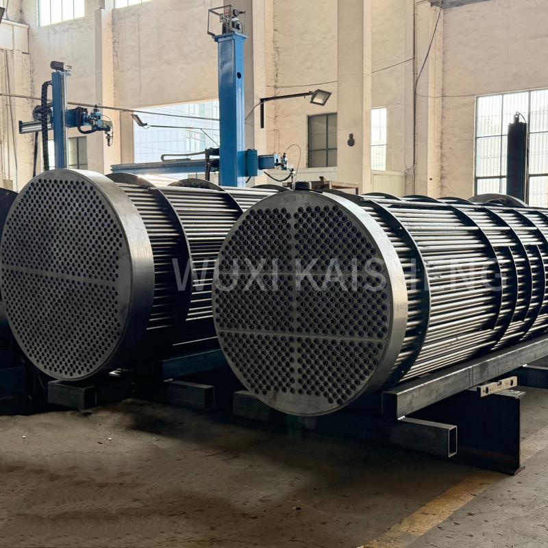
In our practice of engineering support for projects for the production of shell-and-tube heat exchangers, we have repeatedly encountered a situation where finished equipment failed hydraulic tests due to a banal error in choosing the fit between the pipe and the tube sheet.Holes in the tube sheet: tolerances and fits- these are not just reference figures from GOST or ISO, but a critical parameter that determines the service life of the device, its ability to withstand cyclic loads and the risk of leaks at the flaring joint. An incorrect gap of even a few hundredths of a millimeter can lead to the pipe being torn out by the flow of the medium or, conversely, the grille cracking during installation.
Many buyers and even designers mistakenly believe that it is enough to indicate the nominal diameter of the pipe and grate material. Reality dictates different conditions: the pipe material (carbon steel, stainless steel, titanium, copper) behaves completely differently when flared. The stiffness of the material, the yield strength and the coefficient of linear expansion require an individual approach to the selection of the hole tolerance range. In this article, we will break down the specific clearance numbers we use in production for various material pairs, explain the physics of the tight joint process, and provide clear quality control recommendations based on our experience supplying equipment to the energy, oil and gas sectors.
The physics of mating: why a perfect gap is more important than a perfect surface
The expansion process is the plastic deformation of the pipe inside the elastic deformation of the hole of the grating sheet. The key here is to create residual contact pressure after tool removal. If the initial gap between the outside diameter of the pipe and the hole diameter is too large, the pipe must stretch excessively to contact the walls of the hole. This leads to thinning of the pipe wall in the flaring zone, reducing its corrosion resistance and mechanical strength. We have recorded cases where, with gaps greater than 0.5 mm, the pipe wall became thinner by 15-20%, which made the assembly vulnerable to erosive wear in the first months of operation.
On the other hand, too little clearance or interference creates problems during the assembly stage. It is impossible to insert a pipe into a hole with tension manually, and using the force of a hammer often leads to damage to the protective oxide layer or deformation of the pipe end, which interferes with high-quality welding (if a combined technology is provided). Moreover, when assembling a bundle of pipes into a housing, small deviations accumulate, and the pipe may simply not fit into the hole of the next partition. Therefore the questionотверстия в трубной решетке: допуски и посадкиalways balances between the manufacturability of the assembly and the reliability of the final connection.
The optimal clearance ensures uniform distribution of flaring force. When the tool rollers press on the inner surface of the pipe, it expands and is pressed tightly against the walls of the hole. The elastic forces of the lattice sheet material tend to return the hole to its original shape, creating a “squeezing” effect. It is this contact pressure that keeps the pipe from being pulled out under the influence of axial loads and ensures tightness without the use of additional seals. Our statistics show that compliance with the recommended clearances reduces the percentage of defects during hydrotesting from the typical 5-7% to less than 0.5%.
Critical parameters influencing planting selection
When determining the required bore diameter, engineers must consider not only the nominal pipe size, but also a number of dynamic factors. Firstly, there is a difference in the elastic moduli of the materials. For example, when flaring a copper pipe in a steel grid, the behavior of the system will differ from the “stainless steel - stainless steel” pair. Copper deforms more easily, so requires less force, but also less initial clearance to prevent excessive thinning.
Secondly, operating temperature plays a decisive role. If the heat exchanger operates at high temperatures, it is necessary to take into account the difference in the coefficients of linear thermal expansion (CTE) of the pipe and the grid. When heated, one material will expand more than the other. If the CTE of the pipe is higher than that of the grid, the gap during operation will decrease (or the interference will increase), which is good for tightness, but dangerous for the integrity of the grid. If the pipe expands less, the working gap may increase, which will lead to depressurization. In such cases, we recommend artificially adjusting the fit at the design stage by selecting a tighter cold tolerance.
The thickness of the tube sheet also dictates its conditions. For thin gratings (less than 30 mm), the contact area is small, and the requirements for gap accuracy increase, since any taper of the hole or ovality of the pipe immediately affects the strength of the connection. For thick slabs (over 50mm), slightly greater variations are acceptable, but the risk of uneven flaring in depth increases if the tool is not perfectly centered.
Standard clearance ranges for various materials
Based on many years of experience and analysis of the requirements of international standards (TEMA, ASME, GOST R 53683), we have created a table of recommended clearances. This data is the starting point for the design documentation. It is important to understand that these values assume the use of a quality flaring tool with strict diameter restrictions and a professional operator.
| Pipe material | Tube sheet material | Recommended clearance (mm) | Allowable maximum clearance (mm) | Engineer's comment |
|---|---|---|---|---|
| Carbon steel (St3, St20) | Carbon steel (St3, 09G2S) | 0.20 – 0.30 | 0.40 | Classic couple. Easily flared. A gap of up to 0.4 mm is acceptable for manual flaring, but for pneumatic tools 0.25 mm is better. |
| Stainless steel (AISI 304, 316) | Carbon steel | 0.25 – 0.35 | 0.45 | Stainless steel has a high yield strength. More effort is required. The increased gap compensates for the springing of the pipe after the load is removed. |
| Stainless steel (AISI 304, 316) | Stainless steel | 0.20 – 0.30 | 0.40 | Identical materials behave predictably. The risk of cold welding is minimal with proper lubrication. |
| Copper/Brass | Carbon steel | 0.15 – 0.25 | 0.35 | Soft pipe material. A large gap will lead to a strong thinning of the wall. Care is required with flaring force. |
| Titan (Gr.2) | Titanium / Stainless steel | 0.25 – 0.35 | 0.45 | Titanium has a high springback effect. After flaring, the pipe tends to narrow, so the initial contact must be very tight. |
| Double-layer pipes (Bimetal) | Any compatible | 0.30 – 0.40 | 0.50 | It is critical not to damage the inner cladding layer. A special tool with a depth limiter and diameter control is required. |
Pay attention to the column “Permissible maximum clearance”. Exceeding this value does not mean that the connection cannot be created, but it will require multi-stage flaring or the use of special spacers, which is not economically feasible in mass production. In one of our projects for an oil refinery, the supplier of pipe products allowed a negative deviation of the outer diameter of the pipes by 0.4 mm above the norm. The total gap reached 0.7 mm. An attempt to flare such pipes resulted in 30% of the pipes bursting during installation. We had to replace the entire bundle, which delayed shipment by three weeks. This incident taught us to require incoming inspection of each batch of pipes with selective diameter measurements in three sections.
Tolerances for making holes: technology and accuracy
The quality of the hole itself in the tube sheet is no less important than the correct selection of the gap. Even a perfectly calculated tolerance will not work if the hole is tapered, cut, or rougher than normal. Modern production uses several methods for producing holes, each of which imposes its own restrictions on the final tolerance.
Drilling and countersinking.This is the most common method for single and small batch production. However, a standard drill leaves traces of a helix and can lead to axis misalignment. For high pressure heat exchangers we require mandatory subsequent countersinking or reaming. The reamer allows you to obtain a hole with a quality tolerance of IT8-IT9 and a roughness of Ra 3.2-1.6 microns. Such parameters provide excellent tightness. It is important to monitor the wear of the reamer: a dull tool “rivets” the edge of the hole, creating irregularities that prevent the pipe from fitting tightly.
Laser cutting.Increasingly used for thick stainless steel gratings. The laser provides high speed, but leaves a characteristic cut taper and heat-affected zone (HAZ). The edges of the hole may be melted or have carbon deposits. Before flaring, such holes necessarily require mechanical processing (chamfering and calibration), otherwise carbon deposits will act as an abrasive, damaging the pipe, and the taper will lead to uneven compression. Laser cutting tolerances are usually wider, so we allow an additional 0.1mm for post-processing.
Waterjet cutting.Gives a clean cut without HAZ, but the surface of the hole has a matte structure (“sandy” roughness). This can be a plus for grip, but requires careful cleaning to remove the abrasive. Tolerances for waterjet cutting are within ±0.1mm, which is suitable for most industrial applications.
The roughness of the hole walls is a separate issue. A mirror hole that is too smooth (Ra 6.3 µm) creates microcavities where corrosive media can accumulate, causing crevice corrosion. We consider Ra 1.6 – 3.2 µm to be the optimal range for most pairs of materials. This roughness provides a good coefficient of friction for holding the pipe and is easily filled with pipe metal during flaring, ensuring a solid joint.
Control of hole geometry
Before starting the assembly of a pipe bundle, the quality control department must conduct a random inspection of the holes. We use dial head bore gauges to check the diameter at three depth points (inlet, middle, outlet). The permissible taper should not exceed 0.1 mm over the entire length of the fit. The perpendicularity of the hole to the grille plane is also checked. If the deviation angle exceeds 1 degree, the pipe at the entrance will experience bending stress, which will make it difficult to pass through the following partitions and reduce the service life of the unit. In our practice, there was a case when a batch of gratings was manufactured with a violation of perpendicularity due to vibration of the machine. The assemblers had to drill out each hole by hand in order to somehow push the pipes through. This took two days of overtime work.
Flaring technology: from theory to practice
Choosing the right gap is only half the battle. The second half is the proper execution of the flaring operation. Even an ideal gap can be ruined by improper operation of the tool. The flaring process must be strictly controlled by two parameters: the tightening torque (for pneumatic tools) or the number of revolutions/time, and the final pipe diameter.
There are two main control methods:
- Torque control.The tool automatically turns off when the metal resistance reaches a preset value. This method is good for similar materials, but is sensitive to lubrication and the condition of the rollers. If the lubricant has dried out, the tool will stop earlier without pressing the pipe. If the rollers are worn, the torque will increase and the tool may underpressure the pipe, interpreting friction as resistance to deformation.
- Diameter control (calibration).The most reliable method. The operator flares the pipe until the gauge (limit template) no longer passes over the flared part. This method directly guarantees obtaining the desired size and eliminates the human factor “by eye”. We strongly recommend using this method for critical nodes.
The flaring depth is also regulated. The pipe must protrude beyond the grid sheet by a certain amount (usually 2-4 mm) for subsequent flanging or welding. But the zone of plastic deformation itself must be located strictly in the body of the lattice. Under-rolling (when the roller has not reached the end of the working area) creates a channel for leakage. Over-rolling (the roller extends beyond the grid) leads to the formation of a “fungus” at the end of the pipe and thinning of the wall in an unnecessary place, and can also damage adjacent pipes in the bundle.
Lubrication is another critical factor. Using the wrong lubricant can cause scoring. For carbon steels, ordinary machine oils are suitable; for stainless steels and titanium, special pastes with extreme pressure additives (for example, based on molybdenum disulfide) are required. Lack of lubrication or its drying out during operation dramatically increases friction, which can lead to the tool jamming inside the pipe - a situation we call “an assembler's nightmare.” Removing a jammed flaring often ends with the entire pipe being rejected and the hole in the grid being damaged.
Typical errors and methods for eliminating them
Analysis of complaints and returns allows us to identify a number of system errors that are made when the rules for selecting fit and installation technology are ignored.
Mistake #1: Ignoring the ovality of pipes.Pipes, especially thin-walled ones and made from soft materials, can be supplied with ovality. If you insert such a pipe into a round hole and flare it, then in the places of the largest gap the contact will be weak, and in the places of the smallest, local overvoltages will arise. Solution: before assembly, conduct a visual inspection of the ends of the pipes and, if necessary, straighten them with round mandrels. For critical applications, request a certificate from the pipe supplier indicating an ovality of no more than 0.2 mm.
Mistake #2: Repeated flaring.Sometimes the operator, doubting the quality of the first pass, decides to “press” the pipe again. This is a gross violation. The pipe metal has already passed the stage of hardening and plastic deformation. Repeated exposure leads to the appearance of microcracks and a sharp decrease in fatigue strength. If the test shows insufficient torque or diameter, such a pipe should be considered defective. You can try to save it only by complete overcooking (if the design allows), but not by re-flaring.
Mistake #3: Not taking thermal expansion into account when assembling in winter.If assembly is carried out in an unheated workshop at a temperature of -10°C, and operation is expected at +200°C, then the dimensions of the parts will differ significantly. A steel pipe 3 meters long will elongate by about 7 mm when heated by 200 degrees. If the gaps in the partitions are closely matched, this elongation will cause enormous bending stresses. In winter, it is necessary to either warm up the parts to workshop temperature before taking measurements, or make amendments to the assembly flow sheet.
Standards and certification: what to refer to in the documentation
When preparing technical documentation for heat exchangers, it is important to rely on current regulatory documents. In Russia and the CIS countries the main document isGOST R 53683-2009"Heat exchangers. General technical conditions", which is harmonized with European standards. The standard is also widely usedTEMA (Tubular Exchanger Manufacturers Association), classifying requirements depending on the class of the device (R, B, C).
Export contracts often require complianceASME Section VIII Div. 1. ASME Section UG-41 and Appendices detail the strength requirements for pipe-to-grid connections. Particular attention is paid to calculating the pull-out strength. Our engineering department carries out these calculations on a project-by-project basis using actual material strengths verified by 3.1 certificates rather than tabular values. This allows you to select tolerances wisely and guarantee the safety of the pressure apparatus.
Сертификация сварщиков и операторов развальцовки также обязательна. Оператор должен пройти аттестацию на конкретном типе оборудования и с конкретными материалами. Мы ведем журнал аттестации, где фиксируются результаты контрольных образцов (макеты), которые разрушаются в лаборатории для проверки прочности соединения. Только после успешного теста оператор допускается к работе на реальном заказе.
Заключение и рекомендации по закупкам
Правильный выбор параметровотверстия в трубной решетке: допуски и посадки— это инвестиция в надежность вашего теплообменного оборудования. Экономия на качестве трубной продукции, пренебрежение входным контролем диаметров или использование неквалифицированного персонала для развальцовки неизбежно приводят к авариям, простоям производства и дорогостоящим ремонтам. Как показывает наш опыт, стоимость качественного монтажа и точной подгонки составляет ничтожную долю от стоимости всего аппарата, но предотвращает 99% потенциальных проблем с герметичностью.
Если вы планируете заказ теплообменного оборудования или комплектующих (трубных решеток, пучков труб), убедитесь, что ваш поставщик обладает собственным конструкторским бюро и производственной базой, позволяющей контролировать все этапы: от закупки металла до финальных гидроиспытаний. CompanyWuxi Kaisheng Electric Power and Petrochemical Equipment Co., Ltd.специализируется на полном цикле разработки и производства теплообменных аппаратов для самых demanding отраслей. Наш портфель включает титановые кожухотрубные теплообменники, высоконапорные решения по стандарту ASME, гофрированные трубные пучки из нержавеющей стали 316, морская латуни C46400, медно-никелевых сплавов и никелевых сплавов N06625. Мы также производим сложные компоненты, такие как трубные решетки из нержавеющей стали 321, латуни C46400 и сплава C70600.
Наше производство сертифицировано по стандартам PED и ASME, что гарантирует высокую коррозионную стойкость, теплоэффективность и устойчивость к экстремальным давлениям и температурам. Будь то проекты в нефтепереработке, химической промышленности, опреснении морской воды или судостроении, мы предоставляем индивидуальные инженерные решения, адаптированные под конкретные условия эксплуатации заказчика. Используя современное ЧПУ-оборудование для прецизионного сверления решеток и автоматизированные станции развальцовки с контролем момента, мы обеспечиваем 100% соответствие допусков, описанных в этой статье. Доверьте изготовление ответственных узлов профессионалам с подтвержденной репутацией и глобальным опытом поставок.
Свяжитесь с нами сегодня для консультации по вашему проекту, расчета стоимости или запроса коммерческого предложения. Наши инженеры помогут подобрать оптимальные материалы и конструктивные решения, исходя из ваших конкретных условий эксплуатации.
Промышленные теплообменники от производителя | Изготовление трубных решеток на заказ