
Finned tube heat exchangers: types and types
2026-10-04
- Classification and design features of finned tubular heat exchangers
- Extruded (solid) bimetallic heat exchangers
- Heat exchangers with spiral-rolled (high) fins
- Smooth and low fin tubes for severe conditions
- Material selection factors and corrosion protection
- Calculation of thermal efficiency and aerodynamics
- Typical installation and operation errors
- Стандарты качества и сертификация продукции
- Рекомендации по выбору и закупке оборудования
Classification and design features of finned tubular heat exchangers
Finned tube heat exchangers are a fundamental element of modern industrial systems, where heat transfer efficiency directly affects the energy consumption and cost of the final product. In our design and operation practice, we are convinced that the choice of a specific type of fin is not just a technical formality, but a decision that determines the service life of equipment in aggressive environments. The key differences lie in the method of applying the fins and the contact material between the pipe and the fins. An incorrect choice leads to thermal contact resistance or mechanical destruction of the assembly due to thermal expansion.
The market offers many modifications, from spiral-rolled to bimetallic extruded structures. Each type solves specific problems: some are optimized for high-temperature furnaces, others for the corrosive environments of the oil and gas industry. We have observed cases where customers saved at the initial stage by choosing cheap mounted fins, but lost up to 30% of the thermal power after just a year of operation due to oxidation of the contact zone. Understanding the physics of the process and the geometry of the gas flow allows you to avoid such errors. Below we will analyze in detail the main types, their production nuances and real areas of application, based on GOST standards and international norms.
Extruded (solid) bimetallic heat exchangers
Extruded finned tubes are a monolithic structure where the fin and inner tube are made of different metals but are joined at the molecular level through a hot extrusion process. This is the most reliable type of connection, eliminating air gaps between materials. The inner tube is typically made of carbon steel for strength under pressure, while the outer fin is made of aluminum or copper for maximum heat dissipation. The production technology requires complex equipment: the workpiece is heated to a plastic state, then pulled through a matrix that forms a continuous spiral rib.
The main advantage of this design is the absence of thermal contact resistance. In traditional sheathed solutions, even a microscopic gap between the pipe and the fin creates a barrier to heat flow, reducing the overall heat transfer coefficient by 15-20%. In extruded models, this indicator is stable throughout the entire service life. We conducted comparative tests under cyclic heating conditions from -40°C to +300°C: the mounted fins began to “walk” and lose contact after 500 cycles, while the extruded fins remained tight and efficient. This is critical for installations operating under frequent starts and stops.
However, the technology has limitations. The extrusion process imposes requirements on the hardness ratio of the materials. Aluminum extrudes well onto a steel base, but attempts to make all-copper fins on a steel pipe often lead to defects due to the different ductility of the metals. In addition, the height of the fin in extruded versions is usually limited to 16-18 mm. For tasks that require a gigantic heat exchange area in a limited volume, this may not be enough. The production cost of such pipes is 25-30% higher compared to their mounted counterparts, but these costs are recouped by lower operating costs and the absence of the need for frequent maintenance.
The scope of application of extruded heat exchangers is extensive: heating and ventilation systems (heaters), drying chambers in the food industry, air heaters in the energy sector. They are especially in demand in northern regions, where temperature changes are extreme. The GOST R 53677 standard regulates the requirements for such products, including tests for tightness and coating adhesion. When purchasing, it is important to request a certificate of compliance with this standard, since it is difficult to visually distinguish high-quality extrusion from imitation. We recommend using this type for all critical units where equipment downtime leads to colossal losses.
Heat exchangers with spiral-rolled (high) fins
Spiral knurled fins, often referred to as high fins, are created by winding a metal strip onto a smooth pipe and then mechanically deforming it (knurling) to secure it. The tape is pressed tightly against the pipe by rollers, which ensures good, although not perfect, thermal contact. The height of such fins can reach 20-25 mm, which significantly increases the heat transfer surface area compared to extruded analogues. This makes them an ideal solution for low-density gas environments where it is necessary to maximize heat removal per unit volume.
A key feature is the ability to use different combinations of materials. A stainless steel, aluminum or copper strip can be rolled onto a steel pipe. This opens up the possibility of working in chemically aggressive environments where solid aluminum would quickly corrode. For example, in flue gas purification plants (scrubbers) we have successfully used pipes with an alloy steel base and AISI 316L fins. Configuration flexibility allows engineers to precisely select a material for a specific process chemistry without overpaying for a one-piece construction made from an expensive alloy.
However, the knurling method has its weaknesses. The mechanical connection is sensitive to vibrations and sudden thermal shocks. In our practice, there was a case at a pulp and paper mill, where due to a water hammer in a steam pipeline, part of the rolling ribs moved along the pipe, forming an “accordion”. This led to local overheating of the pipe and its depressurization. The problem arose due to insufficient knurling pitch and the lack of additional fixing elements at the ends of the beam. Modern manufacturers are addressing this issue by using laser welding at contact points or increasing pressing force, but risk remains a factor that cannot be ignored in design.
Another important aspect is aerodynamic drag. High fins create significant resistance to gas flow. If the pitch between the fins is too small, the effect of “blocking” the flow occurs, and the fan begins to operate at maximum power, consuming excess electricity. The optimal step is selected experimentally or using CFD modeling for each specific case. Typically it ranges from 2.5 to 4 mm. When ordering equipment, be sure to request a hydraulic resistance calculation to ensure that your existing fans can handle the new load. This type of heat exchanger dominates in the oil refining and gas chemical industries due to its balance between price and performance.
Smooth and low fin tubes for severe conditions
In some industrial processes, increasing surface area becomes a problem rather than an advantage. Smooth pipes or pipes with low fins (height up to 2-3 mm) are used where resistance to pollution, erosion or mechanical damage is important. A classic example is heating viscous oil fractions or working in dusty environments in cement plants. In such conditions, high fins quickly become clogged with dust, soot or paraffin, turning into a heat insulator instead of a heat exchanger. Cleaning the intercostal space becomes impossible without dismantling the equipment.
The design of smooth pipes is as simple and reliable as possible. The absence of thin elements eliminates the risk of their breakage when cleaning with scrapers or hydrodynamic methods. Heat transfer here is carried out mainly due to the long length of the pipes and the high flow rate inside them, and not due to the external area. To compensate for the lower external efficiency, such devices are made more bulky, increasing the number of rows of pipes in the bundle. However, in the long term this turns out to be more profitable: the efficiency of the installation does not decrease over time due to fouling.
Low fin tubes occupy an intermediate position. Small fins (often obtained by rolling from the body of the pipe itself) give an increase in area of about 20-30%, but retain sufficient channels for self-cleaning by the gas flow. We have used such solutions in waste heat boilers operating on associated petroleum gas with a high sulfur content. When condensed, sulfur compounds form aggressive condensate, which quickly corrodes thin aluminum fins. The steel low fins withstood this environment for years, requiring only periodic purging.
When choosing between smooth and ribbed surfaces, a life cycle economic analysis (LCC) must be performed. The cheapness of smooth pipes at the procurement stage can be offset by the huge dimensions of the apparatus and the costs of pumping large volumes of coolant. On the other hand, expensive high-finned units may require production shutdowns every six months for chemical washing. Our recommendation: If the environment contains suspended particles larger than 10 microns or is prone to coking, choose smooth or low-fin solutions made from corrosion-resistant alloys. Ignoring this rule leads to rapid system failure.
| Comparison parameter | Extruded (Bimetallic) | Spiral knurling (High) | Smooth/Low Ribs |
|---|---|---|---|
| Connection type | Molecular (hot extrusion) | Mechanical (rolling/pressing) | Solid or slightly deformed |
| Thermal resistance | Minimal (almost absent) | Average (depending on the quality of knurling) | Absent (monolith) |
| Max. fin height | Up to 16-18 mm | Up to 25 mm and above | 0-3 mm |
| Vibration resistance | High | Medium (risk of bias) | Very high |
| Resistance to pollution | Medium (difficult to clean narrow channels) | Low (fast scoring) | High (easy cleaning) |
| Production cost | High | Average | Low |
| Main Application | Heating, drying, HVAC | Oil and gas, chemistry, air heating | Viscous media, dusty gases |
Material selection factors and corrosion protection
The choice of material for finned tube heat exchangers is dictated not only by thermal conductivity, but also by chemical resistance to the working environment. Aluminum has excellent thermal conductivity (about 200 W/(mK)), but is absolutely not suitable for environments with a pH of 9. In acidic flue gases, aluminum fins can be completely destroyed in one heating season. We encountered a situation at a thermal power plant where an error in the design led to the replacement of thousands of pipes after two years of operation. Therefore, for aggressive environments, the only correct solution is to use stainless steel or special coatings.
Stainless steel (grades 304, 316, 321) provides durability, but its thermal conductivity is 15 times lower than aluminum. To compensate for this drop in efficiency, engineers increase the height and frequency of the fins, or use bimetallic compositions, where the supporting pipe is steel, and the fin is made of a more thermally conductive material with a protective layer. There is also a technology for hot-dip galvanizing steel fins, which protects them from atmospheric corrosion in outdoor installations. The zinc coating serves as a sacrificial anode, taking the blow of corrosion.
At extreme temperatures (above 450°C), conventional aluminum alloys lose strength and begin to “leak.” In such cases, carbon steel fins are used, followed by aluminization (saturation of the surface with aluminum) or the use of heat-resistant alloys. It is important to understand that the coefficient of linear expansion differs between different metals. Steel expands less than aluminum or copper. When heated, this creates stress in the contact area. Designers must install expansion joints or select connection methods that allow micro-displacements without depressurization.
When ordering a batch of heat exchangers, always check the warranty conditions for the anti-corrosion coating. Many suppliers only provide a warranty on the pipe itself, excluding the fins from their area of responsibility, which is a hidden risk for the buyer. Require salt spray testing according to ISO 9227 if equipment will be operated in coastal areas or in areas with chemical emissions. Correct selection of material extends the life of equipment by 3-5 times, which directly affects the ROI of the project.
Calculation of thermal efficiency and aerodynamics
Designing a finned heat exchanger is a matter of finding a balance between thermal output and aerodynamic drag. Increasing the fin area improves heat transfer, but at the same time increases the resistance of the gas path. If the resistance increases too much, the standard fan will not be able to pump the required volume of air, and the outlet temperature will drop, despite the large heat exchange surface. This is a classic beginner mistake: install more pipes to make it warmer, only to have the opposite effect due to a drop in flow.
The fin ratio (the ratio of the total surface area to the internal surface area of the pipe) is a key parameter. For gas media, the optimal coefficient is usually in the range of 15-25. Values above 30 are rarely effective due to the reduction in heat transfer coefficient at the tips of long fins (fin effect). The heat flow fades as it moves away from the base, and the far part of the fin works ineffectively, only creating hydraulic resistance. The engineering calculation must take into account the fin efficiency (η_fin), which depends on the material, thickness and height.
The fin pitch also plays a critical role. Too dense an arrangement of fins (less than 2 mm) leads to the formation of a boundary layer, which “glues” the flows between adjacent turns, worsening turbulization. Too infrequent a step reduces the total area. The optimal step is selected depending on the flow speed: for high speeds you can do it less often, for low speeds - more often. We use specialized flow modeling software that allows us to visualize stagnation zones and optimize geometry before going into production.
Don't forget about the productivity reserve. In real conditions, pipes gradually become dirty, which reduces the flow area and heat transfer. Allow a safety factor of 10-15% for fouling factor when calculating. Ignoring this factor leads to the fact that after a year of operation the system ceases to cope with the load during peak frosts. Always check calculations against the methods described in API 661 or GOST R 53677 to ensure that the assumptions made are correct.
Typical installation and operation errors
Even the most advanced heat exchanger can fail due to installation errors. One of the most common problems is the incorrect orientation of the pipe bundle relative to the air or condensate flow. In heaters operating with moist air, condensate should flow down freely. If the fins are positioned horizontally or at an incorrect angle, water accumulates in the intercostal space. At sub-zero temperatures, this water freezes, expands and ruptures thin fins or even the pipe itself. We have seen the consequences of such accidents: sections turned into useless scrap metal in one winter.
Another common mistake is the lack of compensating elements in the piping. Finned heat exchangers are longer and more rigid. When heated they expand. If the pipe connections are made rigidly, without lens compensators or U-shaped bends, the resulting forces are transferred to the collectors and pipe rolling areas. This leads to leaks at the junction of the pipes and the grille. This is especially true for devices with pipe lengths of more than 6 meters. Design documentation must necessarily include a section on compensation for temperature deformations.
It is also worth mentioning the problem of cavitation and water hammer when starting up steam systems. A sudden injection of steam into a cold heat exchanger causes instantaneous condensation of large volumes of steam, creating a vacuum and a subsequent shock of condensate masses. This can damage the internal partitions and compromise the integrity of the fins on the outside due to vibration. Процедура запуска должна быть плавной, с предварительным прогревом и удалением конденсата через дренажные линии. Персонал должен быть обучен правильным алгоритмам пуска, иначе гарантия производителя может быть аннулирована.
Регулярное обслуживание часто сводится к визуальному осмотру, чего недостаточно. Необходимо периодически проверять герметичность соединений и состояние защитных покрытий. Раз в 3-5 лет рекомендуется проводить ревизию с выборочным вскрытием корпуса для оценки состояния труб в глубине пучка, где коррозия может развиваться незаметно. Игнорирование профилактических мер приводит к внезапным авариям в разгар отопительного сезона, когда время на ремонт ограничено несколькими часами.
Стандарты качества и сертификация продукции
На рынке промышленного оборудования качество оребренных труб варьируется от кустарных изделий до высокотехнологичной продукции, соответствующей мировым стандартам. Для российского рынка ключевым документом является ГОСТ Р 53677-2009 “Теплообменные аппараты. Трубы оребренные”. Этот стандарт регламентирует размеры, допуски, методы контроля качества и требования к материалам. Наличие сертификата соответствия ГОСТ — это минимальное требование, подтверждающее, что продукция прошла входной контроль и испытания. Однако ГОСТ задает лишь базовый уровень; ведущие производители руководствуются более строгими внутренними регламентами.
Для экспортных поставок или работы на объектах международных компаний часто требуются сертификаты по стандартам ASME (США) или PED (Европа). Сертификация по ASME Section VIII гарантирует, что сосуд рассчитан на определенные давления и температуры с высоким запасом прочности. Знак CE подтверждает соответствие европейским директивам по безопасности и экологии. Эти маркировки важны не только для таможни, но и для страховой компании объекта: в случае аварии наличие сертифицированного оборудования упрощает процедуру возмещения ущерба.
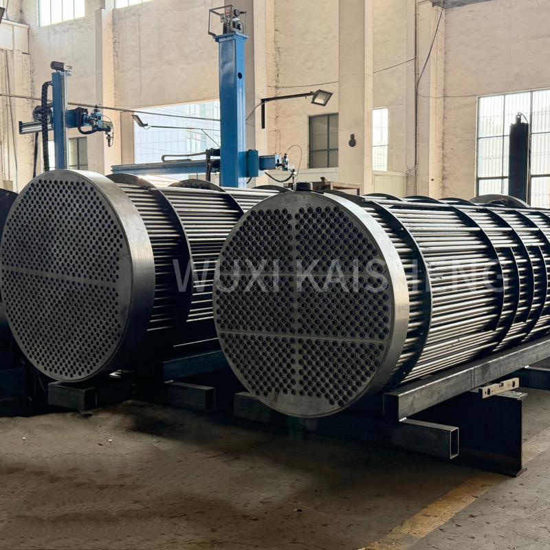
Именно соответствие этим строгим международным нормам является визитной карточкой компании ООО «Уси Кайшэн Электроэнергетическое и Нефтехимическое Оборудование». Специализируясь на разработке и производстве сложного теплообменного оборудования, компания выпускает продукцию, сертифицированную по стандартам ASME и PED, что позволяет поставлять надежные решения заказчикам по всему миру. В ассортименте «Уси Кайшэн» представлены не только классические оребренные трубы, но и высокотехнологичные изделия: титановые кожухотрубные теплообменники, ASME высоконапорные аппараты, гофрированные трубные пучки из нержавеющей стали 316, а также компоненты из морской латуни C46400, медно-никелевых сплавов C70600 и никелевых сплавов N06625. Такой широкий спектр материалов — от углеродистой стали до экзотических сплавов — позволяет компании предлагать индивидуальные решения для самых агрессивных сред, будь то нефтепереработка, химическая промышленность или опреснение морской воды. Продукция «Уси Кайшэн» отличается повышенной коррозионной стойкостью и способностью выдерживать экстремальные давления и температуры, что делает её идеальным выбором для ответственных узлов, где цена ошибки слишком высока.
Особое внимание следует уделять контролю адгезии оребрения. Разрушающий метод контроля (срезание образца ребра) применяется выборочно, но он дает наиболее точную картину прочности соединения. Неразрушающие методы, такие как ультразвуковой контроль или визуальный осмотр под микроскопом, позволяют проверить каждую трубу в партии. Добросовестные производители, такие как «Уси Кайшэн», предоставляют протоколы таких испытаний вместе с партией товара, подтверждая качество металла и надежность соединений. Отсутствие таких документов — красный флаг, сигнализирующий о возможных проблемах с качеством.
При выборе поставщика ориентируйтесь не только на цену, но и на репутацию и наличие собственных испытательных лабораторий. Дешевые трубы с сомнительным происхождением часто изготавливаются из вторичного алюминия или низкокачественной стали, что резко снижает их ресурс. Экономия 10-15% на закупке может обернуться заменой всего теплообменного узла через пару лет. Требуйте предоставления паспортов качества на металл и отчетов о заводских испытаниях перед отгрузкой.
Рекомендации по выбору и закупке оборудования
Выбор типа оребренного теплообменника должен базироваться на детальном техническом задании, учитывающем все параметры процесса: температуру входа и выхода, давление, состав среды, наличие примесей и режим работы (непрерывный или циклический). Не существует универсального решения, подходящего для всех случаев. Для чистых газовых сред с умеренными температурами оптимальны экструдированные трубы, обеспечивающие максимальную эффективность. Для загрязненных потоков или агрессивных химикатов лучше выбрать спирально-накатные трубы из спецсплавов или гладкие трубы с увеличенной поверхностью. В этом контексте опыт компании «Уси Кайшэн» в создании воздушных охладителей, котлов-утилизаторов и специализированных трубных пучков для судостроения и энергетики становится весомым аргументом при выборе партнера, способного реализовать проект любой сложности.
При формировании бюджета закупки учитывайте полную стоимость владения, а не только цену оборудования. Более дорогой аппарат с высоким КПД и долгим сроком службы окажется выгоднее дешевого аналога, требующего частых ремонтов и потребляющего больше энергии. Проведите тендер среди нескольких проверенных производителей, запросив у них не только коммерческое предложение, но и технико-экономическое обоснование выбранной конструкции. Сравните предлагаемые решения по ключевым параметрам: материалу, типу оребрения, гарантийным обязательствам.
Обязательно включите в контракт пункты о шеф-монтаже и пусконаладочных работах силами поставщика. Профессиональный монтаж критически важен для долговечности системы. Ошибки, допущенные на этом этапе, часто невозможно исправить впоследствии без полной замены оборудования. Также предусмотрите возможность поставки запасных секций или ремкомплектов, чтобы минимизировать время простоя в случае непредвиденной поломки. Надежный партнер предложит сервисное обслуживание и мониторинг состояния оборудования в течение всего срока эксплуатации.
В заключение, оребренные трубчатые теплообменники остаются незаменимым инструментом в современной промышленности. Грамотный подход к их выбору, основанный на понимании физических процессов и требований стандартов, позволяет создать энергоэффективную и надежную систему. Не бойтесь задавать вопросы производителям, требовать расчетов и разъяснений. Ваша внимательность на этапе проектирования и закупки станет залогом бесперебойной работы предприятия на годы вперед. Свяжитесь с нами сегодня для получения консультации по подбору оптимального решения для ваших задач.