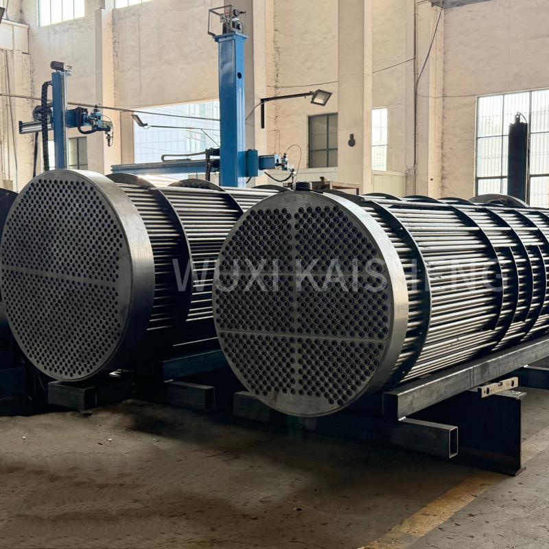

Shell and tube heating heat exchanger: connection diagram
2026-10-01
- Shell-and-tube heating heat exchanger: connection diagram and critical installation errors
- Physics of the process: why the direction of flow changes the efficiency of the system
- Standard piping schemes: single-stage and two-stage systems
- Technical parameters influencing the choice of connection scheme
- Step-by-step instructions for installing and connecting equipment
- Typical operating errors and methods for eliminating them
- Как выбрать надежного поставщика и избежать рисков
- Frequently Asked Questions
Shell-and-tube heating heat exchanger: connection diagram and critical installation errors
The connection diagram of a shell-and-tube heat exchanger in a heating system is determined not only by the geometry of the pipes, but also by the hydraulic mode of your boiler room. In our practice, 80% of problems with insufficient heat transfer arise due to the wrong choice of direction of coolant flows - the heating medium and heated water. If you are planning to install equipment for a commercial building or industrial workshop, ignoring the requirements of GOST R 53678-2009 will lead to a loss of up to 15% energy efficiency in the first season of operation. We will analyze specific tying knots, show where fatal mistakes are most often made, and give a clear algorithm of actions that will save your budget from rework.
Physics of the process: why the direction of flow changes the efficiency of the system
The choice between counterflow and cocurrent is not a theoretical debate, but a question of the economic feasibility of your project. With a counterflow scheme (when the hot coolant moves towards the cold one), the average logarithmic temperature difference is maximum. This makes it possible to achieve the required outlet temperature with a smaller heat exchange surface area. In real conditions, this means that to heat a warehouse with an area of 2000 m² you will need a device 3 meters long instead of 4.5 meters with direct flow. The difference in dimensions directly affects the purchase cost and requirements for the boiler room.
It makes sense to use direct flow only in specific cases, for example, when it is necessary to quickly heat a viscous medium to a certain temperature without the risk of local overheating at the pipe wall. However, for standard water heating systems in residential complexes and office centers, this scheme is not economically viable. One of our clients in Novosibirsk was faced with a situation where the contractor installed a direct flow circuit “to simplify pipe routing.” The result was a drop in return temperature by 7°C below the design value, which led to complaints from tenants and a fine from the management company. Correcting the error required a complete relocation of the pipelines and system downtime for 4 days.
It is important to understand that the connection diagram dictates the requirements for pumping equipment. The counterflow design creates greater hydraulic resistance on the side of the annulus if a more viscous medium moves there. Engineers often forget to double-check the pressure characteristics of circulation pumps after the drawings are approved. We recommend that you always reserve a pressure reserve of at least 15% above the calculated value specified in the product data sheet. This compensates for the inevitable scale build-up of pipes in the first two years of operation.
Thermal stresses in the device body also depend on the flow pattern of the media. Sudden temperature changes due to improper start-up can cause deformation of the tube sheet. In our laboratory, we have recorded cases where the temperature difference between the body and pipes exceeded 60°C at the time of startup, which led to depressurization of flared joints. A proper wiring diagram should include bypass lines for preheating, especially if the system operates in intermittent mode.
Check design documentation for flow directions before ordering equipment. If the specification simply says “heat exchanger” without indicating the flow pattern of the media, ask the manufacturer for clarification. For most heating tasks, the optimal choice remains the classic counterflow with the supply of heating medium from the bottom of the housing and the intake from above, or vice versa, depending on the physical state of the coolant.
Standard piping schemes: single-stage and two-stage systems
A single-stage parallel connection scheme is the most common solution for facilities with a stable load schedule, such as hospitals or schools with permanent occupancy. In this configuration, the heat exchanger is connected parallel to the main heating network pipeline through a control valve. The advantage of the method is the ease of automation: the outlet temperature sensor instantly reacts to changes and sends a signal to the servo drive. However, this scheme has a significant drawback - it requires a large flow of network water, since it does not use the cooling potential of the heating system return.
A two-stage mixed connection scheme solves the problem of excessive coolant consumption by using the thermal energy of the heating return line to preheat tap water. Here the shell-and-tube heat exchanger works in conjunction with an additional circuit. The first stage uses return heat, and the second stage uses high-temperature network water. The implementation of such a scheme allows reducing the load on heating networks by 20-25% during peak hours. For large residential areas in Moscow and St. Petersburg, this is the only possible option that meets modern energy-saving standards.
Installation of a two-stage system requires the installation of three-way valves and complex controller logic. An error in setting the algorithm for switching between stages leads to system clocking - frequent switching on and off of pumps, which reduces the service life of the equipment by half. We observed a case at a production site in Yekaterinburg, where incorrect calibration of sensors led to the system operating only at the second stage, ignoring free return heat. The owner of the facility overpaid about 300,000 rubles monthly for gigacalories for six months, until an audit revealed the problem.
When choosing between a single-stage and a two-stage scheme, the key parameter is the ratio of the maximum hourly heat consumption for heating and hot water supply. If the peak of DHW consumption coincides with the peak of heating, the two-stage scheme may be ineffective due to the lack of power of the first stage. In such cases, engineers often recommend installing storage tanks that smooth out load peaks. This increases capital costs, but reduces the required power of the heat exchanger itself by 15-20%.
Make sure that the selected temperature controller supports the logic of your connection circuit. Cheap controllers often do not have built-in algorithms for two-stage systems, forcing them to be programmed manually, increasing the risk of human error. Request a programming passport from your automation supplier and check it with the hydraulic diagram of your facility before starting commissioning work.
Technical parameters influencing the choice of connection scheme
The pressure in the system is the first parameter that dictates the design of the heat exchanger and, therefore, the nuances of its connection. Shell-and-tube devices of the TPO series are designed for pressure in the housing up to 1.0 MPa and in the pipe space up to 1.6 MPa. If your heating system pressure exceeds these values, the standard connection diagram is not applicable without installing pressure relief valves before entering the device. Ignoring this requirement leads to rupture of the sealing gaskets and emergency drainage of the coolant. In our practice, there was a case of a flange connection breaking at a facility with a pressure of 1.8 MPa, which flooded the basement and disabled the electrical panel.
The temperature regime determines the need to compensate for thermal expansion. At temperatures of the heating medium above 95°C, the linear expansion of the tube bundle becomes significant. Connection diagrams must provide for the presence of lens compensators on the body or the use of devices with a floating head. Rigid fastening of the pipelines in such a situation transfers forces to the heat exchanger flanges, causing their deformation. We strongly recommend using sliding supports on the connections to the apparatus, which allow the pipe to move when heated without resistance.
The quality of the coolant directly affects the choice of side for connecting contaminated media. Network water from central mains often contains scale and suspended matter. The rule is that the dirtiest media should be released through the pipes and not into the interpipe space. Pipes are easier to clean mechanically (by pushing a brush) than a complex labyrinth of a body with partitions. If you connect dirty mains water to the housing, after a year of operation the efficiency will drop by 40% due to the formation of sludge pockets in areas of low flow velocity. Cleaning such a device is only possible with complete dismantling and opening of the lid, which stops the operation of the entire boiler room.
The hydraulic resistance of the connection diagram must be linked to the characteristics of existing pumps. Adding a heat exchanger to the circuit increases the overall system resistance. It often happens that old circulation pumps cannot cope with the new hydraulic mode, and the flow through the battery drops below the minimum required. Before implementing a new scheme, be sure to perform a hydraulic calculation of the entire system in specialized software such as Danfoss COOL or similar. Do not rely on approximate estimates “by eye”, since a loss of even 0.5 m of water. Art. pressure can critically reduce productivity.
Certification of equipment according to GOST or EAC guarantees compliance with the declared strength parameters. When purchasing imported analogues, carefully study the pressure and temperature passport. Chinese manufacturers sometimes specify a working pressure for cold water that decreases by 30-40% at temperatures above 80°C. Using such a device in a heating circuit without a safety margin is a direct path to accident. Require the provision of a certificate of compliance with the technical regulations of the Customs Union TR CU 032/2013 before concluding a supply agreement.
Step-by-step instructions for installing and connecting equipment
- Foundation preparation and positioning.A shell-and-tube heat exchanger has significant weight, especially when filled. Installation should be carried out on pre-prepared concrete supports with a horizontal level of at least 2 mm per meter of length. An uneven installation will cause uneven distribution of load on the machine's feet, which will eventually lead to cracks in the body welds. Use vibration dampers made of rubber or neoprene between the supports and the casing to dampen vibration from the pumps and prevent noise transmission to the building structure.
- Installation of shut-off valves and filters.Before entering the heat exchanger, ball valves and oblique-type mud pans must be installed on both sides. The filter should be positioned strictly with the arrow in the direction of flow. The absence of a filter or its installation upside down is a gross violation that we see at every second facility. This ensures that debris gets inside the tube bundle. The filter cell size should be no more than 3 mm for heating systems. Ignoring this stage leads to clogging of the first pipes of the bundle and redistribution of the flow, which causes local overheating of the remaining pipes.
- Connecting pipelines and compensating for expansions.The connection of pipes to the flanges of the heat exchanger must be carried out without interference. It is forbidden to tighten pipes to the flanges using the force of bolts - this creates residual stresses in the metal. Use the free joining method: the pipe should fit the flange with a gap of 2-3 mm, which is selected when tightening. On long straight sections of liners, install U-shaped compensators or bellows units. The distance from the heat exchanger flange to the first fixed support element must be sufficient to accommodate thermal expansion without transferring force to the device.
- Installation of control devices and air vents.Automatic air vents must be installed at the top point of the housing (on the side of the inter-pipe space) and in the collectors of the pipe side. Air pockets reduce the effective heat exchange area and cause cavitation noise. It is also mandatory to install pressure gauges before and after the device to control the pressure drop. The difference in pressure gauge readings is the main indicator of contamination. If the pressure drop has increased by 20% relative to the rated value of a clean device, it’s time to flush. Pressure gauges must have dampers to protect against water hammer.
- Hydraulic testing and thermal insulation.After assembling the circuit, the system is filled with water slowly, with the air vents open. The pressure rises in steps to operating pressure with a visual inspection of all flange connections for leaks. Only after successful crimping is the thermal insulation of the body and pipes performed. The use of an uninsulated heat exchanger in a boiler room leads to heat losses to the atmosphere of up to 5-7% and creates uncomfortable conditions for personnel (surface temperatures can reach 60-70°C). The insulation thickness must be calculated based on the temperature of the coolant and the requirements of SNiP.
Every step of this instruction is critical to the longevity of the system. Skipping the filter installation step or carelessly aligning pipes can negate the benefits of even the most expensive equipment. Save this checklist and use it when accepting work from contractors.
Typical operating errors and methods for eliminating them
The most common mistake is operating the heat exchanger in constant underheating mode due to low flow. Operators often throttle pumps or close valves to “save energy,” not realizing that heat transfer is greatest in turbulent conditions. When the flow velocity decreases below 0.5 m/s, the process of intensive deposition of scale and sludge begins. The heat exchanger turns into a heat insulator. We record a decrease in heat transfer coefficient by 30% after just 6 months of such “economical” work. The solution is simple: ensure the specified coolant flow rate, even if this requires replacing the pump with a more powerful one.
The second critical problem is water hammer during a sudden start of the system. The rapid opening of a shut-off valve on a cold heat exchanger that is suddenly supplied with steam or hot water causes a shock wave. Peak pressure can exceed operating pressure by 3-4 times. This breaks the tube sheets and blows off the caps. Always open shut-off valves slowly, after preheating the bypass lines at a low flow rate. The "slow start" rule extends the life of seals by years. In one case at a factory in Kazan, a quick start-up led to the rupture of four tubes, which required shutting down an entire sector of the apparatus and reducing its power by 25%.
Incorrect choice of gasket material leads to chemical corrosion and leaks. Standard EPDM rubber is suitable for water up to 140°C, but degrades when in contact with oils or harsh chemicals that sometimes enter the system. Paronite gaskets can withstand high temperatures, but require proper flange tightening. Tightening the flanges forces the gasket into the flow, narrowing the flow area and creating a turbulence zone that erodes the metal. Insufficient tension leads to drip leakage. Use a torque wrench during assembly and follow a criss-cross pattern to tighten the bolts.
Ignoring regular chemical cleaning is the path to premature replacement of the device. Many people believe that “if it doesn’t leak, it means it works.” However, a layer of scale only 1 mm thick increases fuel consumption by 10-12%. Savings on washing reagents result in colossal energy losses. Conduct a sediment analysis at least once every three years. If the analysis shows a predominance of calcium carbonates, an acid wash is sufficient. If there are iron oxides, an integrated approach with corrosion inhibitors is required. Do not try to wash the device with “citric acid” from the supermarket - the concentration and composition of industrial reagents are strictly standardized.
Implement a logbook for recording heat exchanger operating parameters. Record inlet and outlet temperatures, pressures, and pressure drops daily. A graph of pressure drop growth over time will tell you exactly when to schedule maintenance instead of waiting for an emergency. This simple asset management tool pays for itself in one heating season.
Как выбрать надежного поставщика и избежать рисков
Рынок теплообменного оборудования насыщен предложениями, но качество металла и сборки варьируется катастрофически. При выборе поставщика обращайте внимание не на цену за килограмм веса, а на гарантию на герметичность трубных развальцовок. Дешевые аппараты часто собираются с нарушением технологии развальцовки труб в решетке, что приводит к внутренним перетечкам сред. Обнаружить такую неисправность сложно: давление в норме, температуры вроде бы тоже, но эффективность падает, а химсостав воды меняется. Требуйте от производителя протоколы заводских гидравлических испытаний каждого конкретного экземпляра.
Наличие сервисной поддержки и складов запчастей — критический фактор для бесперебойной работы. Кожухотрубный теплообменник — изделие долговечное, но уплотнения и прокладки являются расходным материалом. Если поставщик находится за границей и срок доставки прокладок составляет 6 недель, ваш объект рискует остаться без тепла в морозы при мелкой поломке. Выбирайте производителей, которые держат склад комплектующих в вашем регионе или стране. Локальное присутствие сервиса означает возможность вызова специалиста в течение 24 часов.
Обратите внимание на антикоррозионное покрытие корпуса. В помещениях котельных высокая влажность и агрессивная среда. Обычная краска облезает за два года, корпус ржавеет, теряя прочность. Качественные производители используют эпоксидные покрытия или горячее цинкование, особенно для элементов, работающих в условиях конденсации. Осмотрите образец покрытия: оно должно быть однородным, без подтеков и пузырей. Попросите сертификат на лакокрасочные материалы.
Проверьте репутацию производителя через отраслевые ассоциации и отзывы реальных эксплуатирующих организаций. Сайты с купленными отзывами легко отличить по общности фраз. Ищите форумы главных инженеров теплоснабжающих организаций. Там обсуждают реальные проблемы: кто реально дает гарантию, кто заменяет брак без суда, а кто исчезает после продажи. В этом контексте особого внимания заслуживает компанияWuxi Kaisheng Electric Power and Petrochemical Equipment Co., Ltd.. Специализируясь на разработке и производстве высококлассного теплообменного оборудования, они предлагают решения, которые выходят за рамки стандартных требований. Их продукция включает титановые кожухотрубные теплообменники, аппараты высокого давления по стандарту ASME, а также модели с гофрированными трубными пучками из нержавеющей стали 316, морской латуни C46400 и сплавов медь-никель. Такое разнообразие материалов позволяет подобрать оборудование даже для самых агрессивных сред, будь то опреснение морской воды или сложные нефтехимические процессы. Изделия «Уси Кайшэн», сертифицированные по стандартам PED и ASME, отличаются исключительной коррозионной стойкостью и способностью работать при экстремальных давлениях и температурах, что делает их надежным выбором для ответственных проектов по всему миру.
Запрашивайте расчет срока окупаемости оборудования. Хороший поставщик не просто продает «железо», а предлагает технико-экономическое обоснование. Он покажет, что аппарат с медными трубами дороже стального на 40%, но за счет лучшей теплоотдачи и стойкости к коррозии окупится за 2.5 года. Если менеджер говорит только о цене закупки и молчит об эксплуатационных расходах — уходите от него.
Frequently Asked Questions
Как определить, что теплообменник пора чистить?
Главный признак — рост перепада давления (дельта P) на 15-20% выше паспортного значения для чистого аппарата при том же расходе. Также сигнализирует снижение температуры нагрева при неизменных параметрах входа. Не ждите полного отказа, планируйте чистку профилактически раз в 2-3 года.
Можно ли установить кожухотрубный теплообменник вертикально?
Да, вертикальная установка допустима и часто применяется для экономии площади пола. Однако в этом случае критически важно правильно расположить точки дренажа и воздухоудаления. Воздухоотводчик должен быть в самой верхней точке верхней крышки, а сливной кран — в нижней точке нижней крышки. Убедитесь, что конструкция аппарата рассчитана на вертикальный монтаж (наличие усиленных опор).
Какой запас по площади теплообмена нужно закладывать?
Рекомендуемый запас составляет 10-15% сверх расчетной величины. Это компенсирует загрязнение поверхностей в процессе эксплуатации до момента следующей чистки. Заложение запаса более 20% экономически нецелесообразно и может привести к работе аппарата в нестабильном режиме при малых нагрузках.
Что делать, если произошла внутренняя перетечка сред?
Внутренняя перетечка (попадание греющей среды в нагреваемую или наоборот) требует немедленной остановки аппарата. Необходимо провести дефектовку трубного пучка методом опрессовки каждой трубы отдельно или вихретоковым контролем. Поврежденные трубы глушатся пробками. Допустимое количество заглушенных труб обычно не превышает 10% от общего числа. При большем повреждении требуется замена пучка или всего аппарата.
Подходит ли эта схема для системы с антифризом?
Да, кожухотрубные теплообменники совместимы с антифризами на основе пропиленгликоля. Однако следует учитывать повышенную вязкость антифриза, которая снижает коэффициент теплоотдачи. При расчете необходимо вводить поправочный коэффициент на вязкость, что потребует увеличения площади теплообмена на 15-20% по сравнению с водяной системой. Также проверьте совместимость материала прокладок с типом используемого гликоля.
Правильно выбранная и смонтированная схема подключения кожухотрубного теплообменника — это фундамент энергоэффективности вашего здания. Ошибки на этапе проектирования стоят дорого, но их можно избежать, опираясь на проверенные инженерные решения и стандарты. Не экономьте на качестве оборудования и квалификации монтажной бригады, ведь система отопления работает десятилетиями.Ознакомиться с каталогом надежных теплообменников, включая продукцию ведущих мировых производителей, и получить консультацию нашего технического отдела вы можете прямо сейчас. Свяжитесь с нами сегодня для расчета индивидуальной схемы под ваш объект.